
K 2500 Truck 4WD V8-379 6.2L DSL VIN C FI (1989)
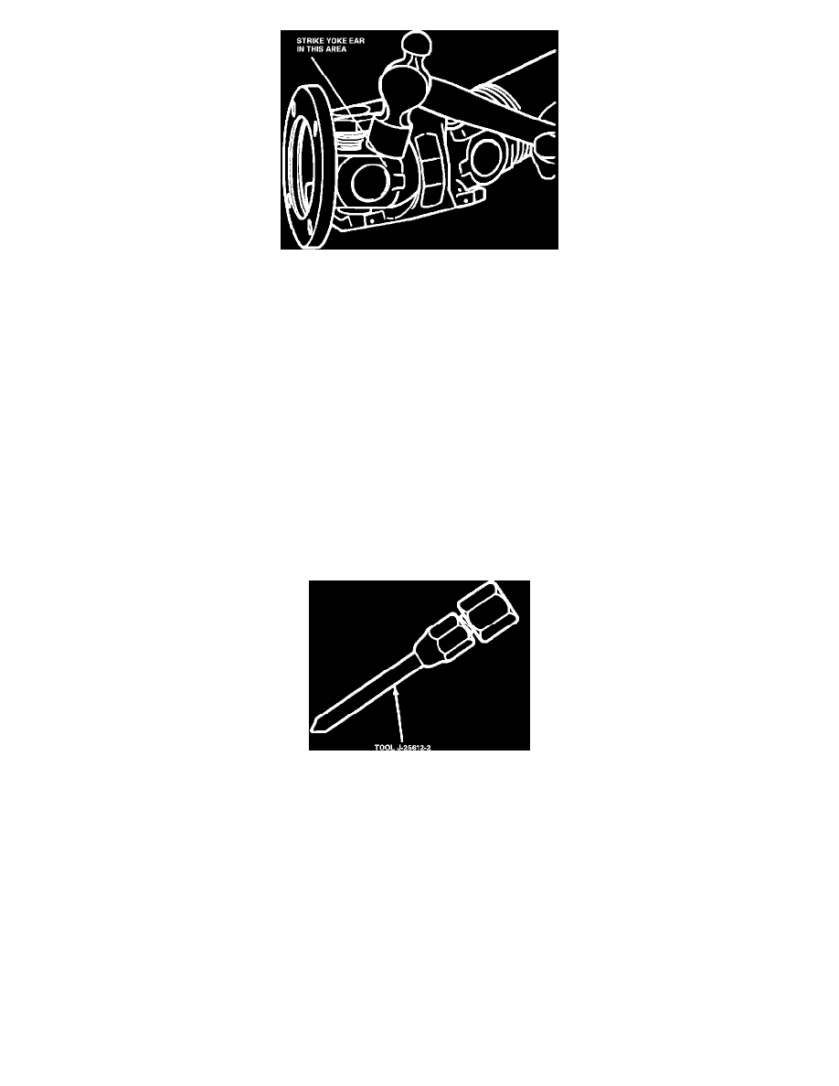
Fig. 22 Relieving Binding Condition At Point C
ASSEMBLY
Ball Socket & Constant Velocity Joint
During assembly, make sure that marks made during disassembly, Fig. 12, are aligned to maintain balance.
1.
To install centering ball onto stud, use tool C-4365 or equivalent, and drive ball until it can be seen that ball has seated firmly against shoulder at
base of stud.
2.
To install cross assembly, install one bearing cup part way into one side of yoke and turn this yoke to the bottom. Insert cross into yoke so that the
trunnion seats into bearing, Fig. 18. Install opposite bearing cup part way, Fig. 19. Make sure that both cross journals are started straight into both
bearing cups.
3.
Press bearing cups, while moving cross to ensure free movement of trunnions in bearing. If any binding is felt, stop pressing and check needle
bearings to make sure that needle bearings have not been trapped under the ends of the cross journals.
4.
As soon as one of the retaining ring grooves clears the inside of yoke, stop pressing and install retaining ring.
5.
Continue to press until opposite retaining ring can be snapped into place. If difficulty is encountered, strike the yoke firmly in locations shown in
Figs. 20, 21 and 22, to spring the yoke ears slightly.
6.
Lubricate center ball and socket, and assemble other half universal joint, if disassembled.
Lubrication
Fig. 23 Lubrication Fitting Adapter