
K 3500 Truck 4WD V8-5.7L VIN R (1998)
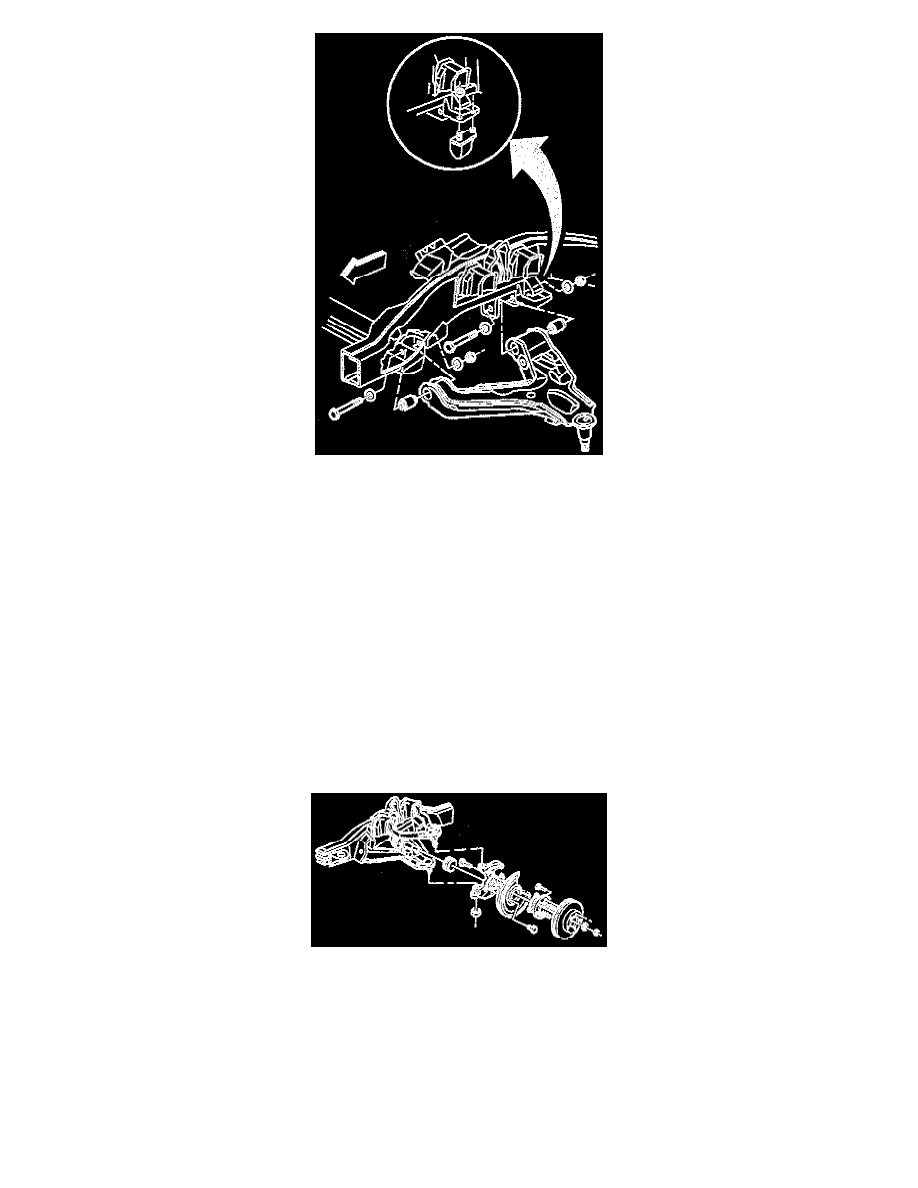
4. Install the bolts in the direction shown.
5. Install the new nuts.
Tighten
^
Tighten the front nut prior to tightening the rear nut.
^
Tighten the nuts with the control arm at the proper Z height.
^
Tighten the nuts to 165 Nm (121 ft. lbs.).
NOTICE: Always use the correct fastener in the proper location. When you replace a fastener, use ONLY the exact part number for that
application. The manufacturer will call out those fasteners that require a replacement after removal. The manufacturer will also call out the
fasteners that require thread lockers or thread sealant. UNLESS OTHERWISE SPECIFIED, do not use supplemental coatings (paints, greases, or
other corrosion inhibitors) on threaded fasteners or fastener joint interfaces. Generally, such coatings adversely affect the fastener torque and joint
clamping force, and may damage the fastener. When you install fasteners, use the correct tightening sequence and specifications. Following these
instructions can help you avoid damage to parts and systems.
6. Prelube the steering knuckle seed.
7. Start the drive axle through the hub.
8. Connect the ball joint to the knuckle.
9. Install the ball joint nut.
Tighten
Tighten the nut to 128 Nm (94 ft. lbs.).
10. Install the cotter pin. Bend the pin ends against the side of the nut.
11. Install the torsion bar adjuster arm.
11.1. Slide the bar rearward in order to install the sides of the nut.
11.2. Using the J 36202, load the torsion bar.
11.3. Install the adjuster bolt and screw the bolt down to the installation mark.