
S15/T15 4WD P/U V6-262 4.3L VIN W CPI (1992)
Control Module: Description and Operation
TCCM Inputs and Outputs
TCCM Inputs
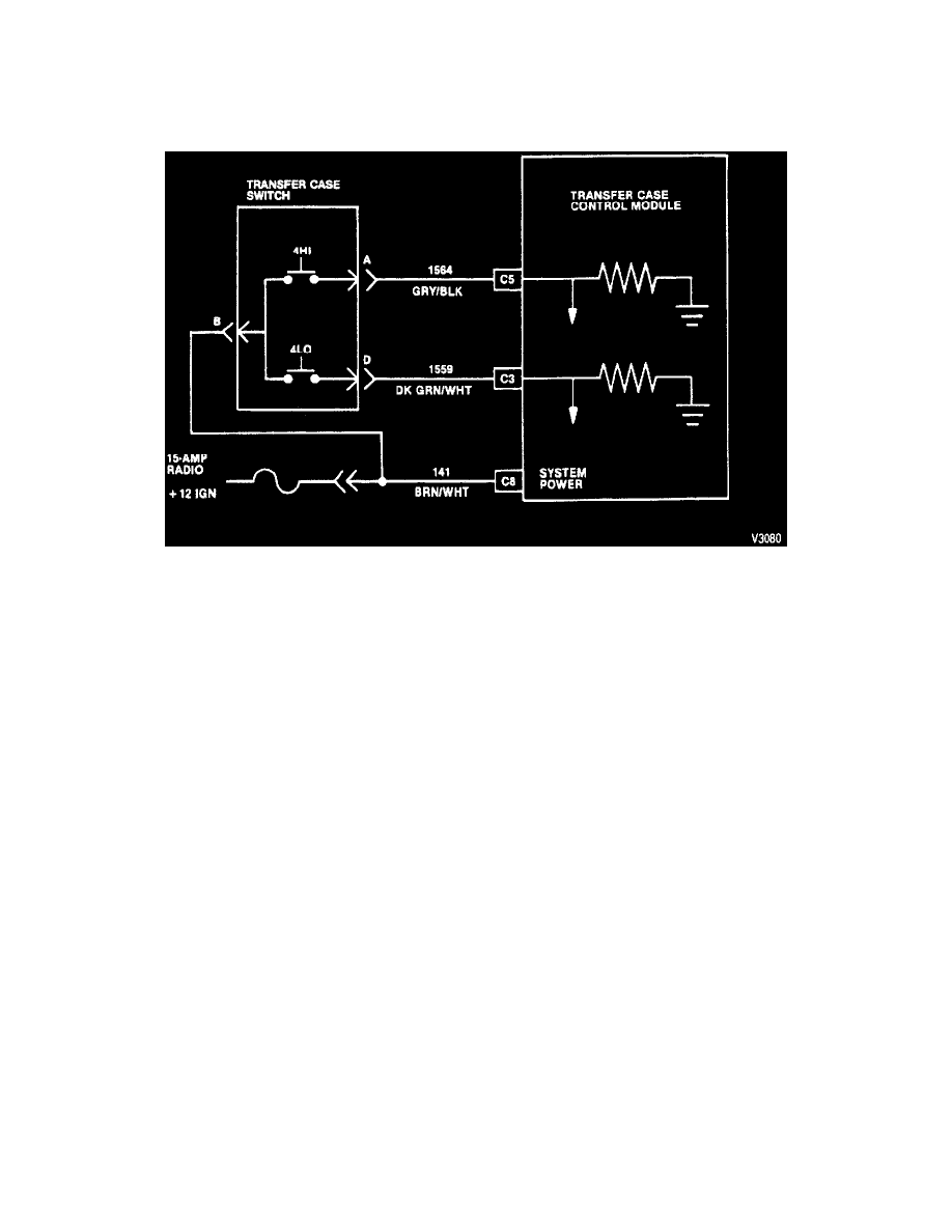
4WD Selector Switch Wiring Schematic
OPERATION
2HI to 4HI selector switch input
When the transfer case is in 2HI and the operator presses the 4HI area of the rocker switch, the 4HI contacts of the selector switch close, connecting
circuits 141 and 1564, and furnishing 12-volts to pin C5 of the TCCM connector. The 12-volt signal at pin C5 commands the Transfer Case Control
Module (TCCM) to signal the electric-shift motor to shift into 4HI. The contacts return to the open position as soon as the switch is released.
4HI to 2HI Selector Switch Input
If the transfer case is in 4HI and the operator presses the 4HI area of the rocker switch, the 4HI contacts of the selector switch close, connecting
circuits 141 and 1564 and furnishing 12-volts to pin C5 of the Transfer Case Control Module (TCCM) connector. The 12-volt signal at pin C5
commands the TCCM to signal the electric-shift motor to shift into 4HI. Again, the contacts return to the open position as soon as the switch is
released.
2HI to 4HI to 4LO Selector Switch Input
When the operator presses the 4LO area of the rocker switch while the transfer case is in either 2HI or 4HI, the 4LO contacts of the selector switch
close, connecting circuits 141 and 1559, and furnishing 12-volts to pin C3 of the Transfer Case Control Module (TCCM) connector. The 12-volt
signal at pin C3 commands the TCCM to signal the electric-shift motor to shift the transfer case into 4LO. Once more, the contacts return to the open
position as soon as the switch is released.
TCCM Outputs