
S15/T15 Jimmy 2WD L4-119 1.9L VIN A 2-BBL (1983)
Wiper Motor: Description and Operation
Permanent Magnet Motor
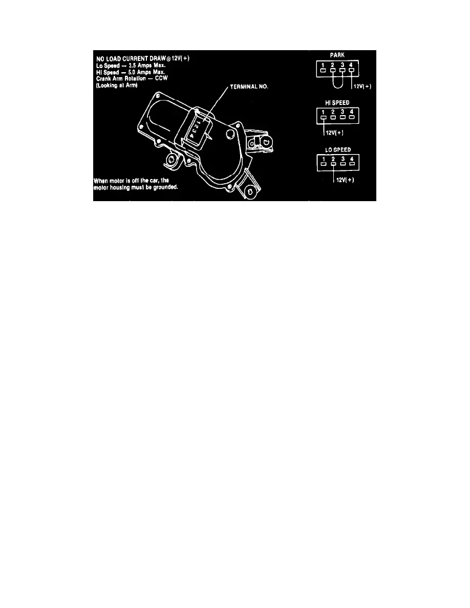
Fig. 10 Permanent magnet type windshield wiper motor.1982---87 S/T 10 & 15 models
1982---87 S/T 10 & 15 MODELS
Wiper motor internal components, including permanent magnet fields, armature, brush holder and gear train, are enclosed in a die cast aluminum
housing with a plastic cover, Fig. 10. The brush holder contains a circuit breaker and park switch as well as common, low and high speed brushes, and it
is located at the gearbox end of the motor.
The common brush is connected to ground through the wiper motor ground strap. Battery voltage is supplied to the wiper switch and motor park
switch fixed contacts through a fuse in the fuse block. Motor speeds are determined by supplying voltage through the wiper switch to the low or high
speed motor brush, and when wiper switch is in off position, voltage supplied to the motor park switch allows wipers to park at the bottom of their travel.
Pulse wiper operation, if equipped, is controlled by a variable resistor in the wiper switch and by a pulse module connected between the wiper motor and
switch.
Standard (Non-Pulse) Wiper Operation
When ignition is on, battery voltage is supplied to low and high speed contacts in the wiper switch and to motor terminal 4, Fig. 10. Placing wiper
switch in low or high position completes the feed circuit to motor terminal 2 (low speed brush) or terminal 1 (high speed brush), Fig. 10. Current flows
through the armature to ground through the common brush, and the motor runs at the selected speed.
Placing wiper switch in off position connects the motor low speed brush to park switch terminal 3, Fig. 10. Current flows through the closed park
switch contacts, allowing the motor to run at low speed. When wipers reach their lowest point of travel, a cam on the motor output shaft opens the park
switch through an actuating lever, and the motor stops.
Pulse Wiper Operation
In addition to standard wiper system components, models with pulse wipers use a pulse control module and a wiper switch with a variable resistor and
additional contacts to control pulse module operation. Current flow between the wiper motor and switch, and battery voltage to the switch pass through
the pulse control module. However, when the wiper switch is in off, low or high position, the module does not affect system operation.
When the wiper switch is in delay position, voltage is supplied to the pulse module timer through the variable resistor. When the timer circuit becomes
fully ``charged,'' the timer switch closes, and voltage is supplied to the motor through a second delay terminal in the wiper switch. As the motor begins to
operate, the park switch closes, the timer switch opens, and voltage is supplied to the motor through a third delay contact which is linked to the park
switch in the wiper switch. When wipers complete their cycle, the park switch opens, the motor stops, and the timer begins to ``recharge.''
This cycle repeats as long as wiper switch is in delay position. Delay period is controlled by varying resistance in the pulse module timer feed circuit.