
S15/T15 Sonoma P/U 4WD V6-262 4.3L VIN W CPI (1994)
Differential Carrier: Adjustments
Aluminum Case Front Drive Axle
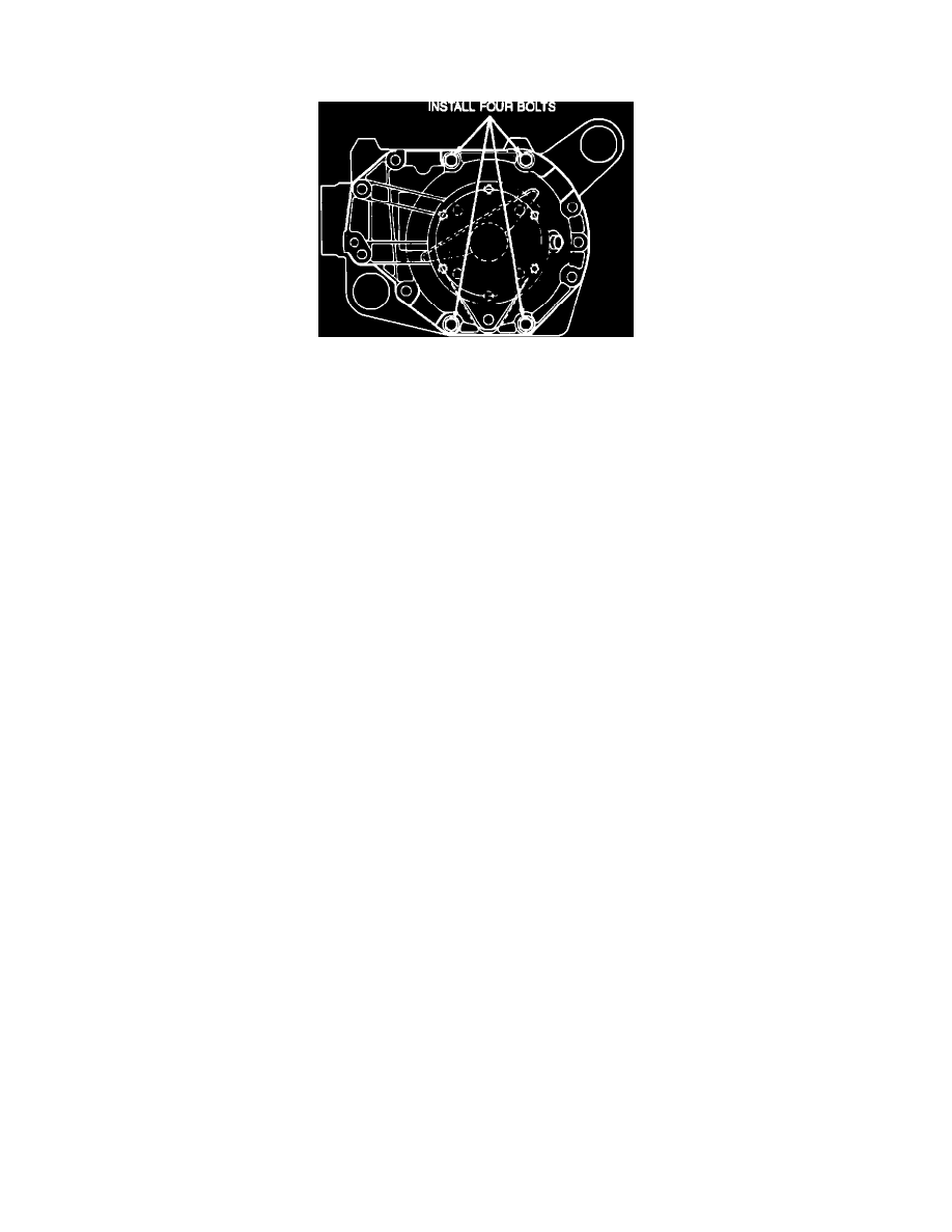
Fig. 23 Case Assembly For Backlash Adjustment
1.
Turn lefthand adjusting sleeve in toward differential case using side bearing adjuster wrench tool No. J-33792 or equivalent, until backlash is felt
between ring and pinion gears.
2.
Clean carrier half mating surfaces, then install halves together without using any sealer. Install four case bolts, Fig. 23, and torque to 37 ft. lbs. If
carrier halves will not make complete contact, back out the right hand adjusting sleeve.
3.
Tighten right hand adjusting sleeve using side bearing adjuster wrench tool No. J-33792 or equivalent until no backlash is present (approximately
100 ft. lbs.), then torque lefthand adjusting sleeve to approximately 100 ft. lbs.
4.
Mark relation of adjusting sleeves to carrier halves so that the notches in adjusting sleeves can be counted when turned.
5.
Turn righthand adjusting sleeve out two notches and left hand sleeve in one notch using side bearing adjuster wrench tool No. J-33792 or
equivalent.
6.
Rotate axle case several times to seat bearings, then mount dial indicator.
7.
Install a small button on indicator stem and position so that contact can be made near heel end of tooth angle. This will provide an accurate
backlash reading. Backlash should be .003-.010 inch, with a preferred reading of .005-.007 inch.
8.
If backlash is not within specifications, readjust adjusting sleeves as necessary. Do not install adjusting sleeve locks at this time.
9.
Mark position of righthand adjusting sleeve, then loosen sleeve to relieve contact between righthand side bearing and differential case.
10.
Remove four carrier bolts and separate the carrier halves.
11.
Apply sealer No. 1052357, Loctite 514 or equivalent to mating surface of one carrier half, then assemble two halves together with all ten attaching
bolts. Torque bolts to 30-40 ft. lbs.
12.
Set righthand adjusting sleeve in position according to mark made previously, then install both adjusting sleeve locks and torque to 62-88 inch
lbs.