
Savana 2500 V8-6.6L DSL Turbo (2008)
2. Ignition OFF, disconnect the harness connector (splice pack comb) at JX200. Install a 3-amp fused jumper wire between JX200 terminal A and
terminal D, harness side.
3. Ignition ON, with a scan tool, attempt to communicate with the instrument panel cluster (IPC). Communication should be available.
‹› If no communication, test the serial data circuit for a short to ground, a short to voltage or an open/high resistance between the IPC and the
DLC. If the circuit tests normal, replace the IPC.
4. Install another 3-amp fused jumper wire to JX 200 terminal A, harness side.
5. With IPC communications established, use the other end of the jumper wire to connect all other terminals, harness side, one at a time and verify
that low speed communication remains available to the IPC.
Important: Allow communications for 5 seconds after connecting a module with the jumper to determine if communication is interrupted
or not.
‹› If low speed communication is interrupted after connecting an individual module at JX200, test the serial data circuit between JX200 and the
last module connected for a short to voltage and short to ground. If the circuit tests normal, replace the module that caused no communication.
Repair Instructions
Perform the Diagnostic Repair Verification after completing the repair. See: Testing and Inspection/Diagnostic Trouble Code Tests and Associated
Procedures/Verification Tests and Procedures
*
GMLAN Wiring Repairs
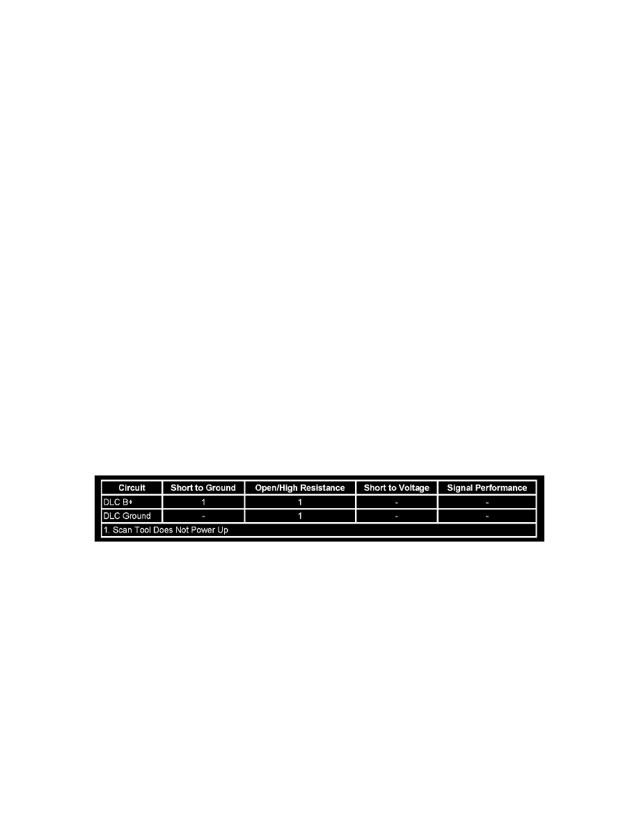
Scan Tool Does Not Power Up
Scan Tool Does Not Power Up
Diagnostic Instructions
*
Perform the Diagnostic System Check - Vehicle prior to using this diagnostic procedure. See: Testing and Inspection/Initial Inspection and
Diagnostic Overview/Diagnostic System Check - Vehicle
*
Review Strategy Based Diagnosis for an overview of the diagnostic approach.
*
Diagnostic Procedure Instructions provides an overview of each diagnostic category.
Diagnostic Fault Information
Circuit/System Description
The data link connector (DLC) is a standardized 16 cavity connector. Connector design and location is dictated by an industry wide standard, and is
required to provide the following:
*
Scan tool B+ voltage at terminal 16
*
Scan tool ground at terminal 4
*
Common ground at terminal 5
Diagnostic Aids
*
The scan tool will power up with the ignition OFF. Some modules however, will not communicate unless the ignition is ON and the power mode
master (PMM) module sends the appropriate power mode message.
*
If the B+ circuit, ground circuits, and connections of the DLC are functioning properly, the malfunction must be due to the scan tool/CANdi
module.
Circuit/System Testing
1. Test for less than 2.0 ohms between the ground circuits terminal 4 of the DLC and ground, and terminal 5 of the DLC and ground.
‹› If greater than the specified range, test the ground circuit for an open/high resistance.