
Sierra 3500 Denali 2WD V8-6.0L (2011)
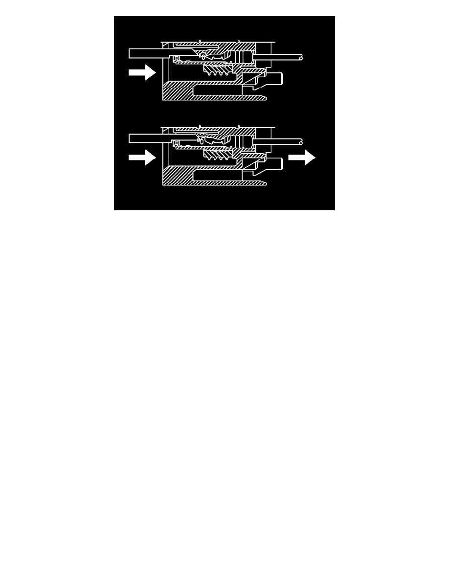
9. The illustration shows a cutaway view of the connector to aid the technician in releasing the terminal retainer.
10. Repair the terminal by following the Repairing Connector Terminals (Terminated Lead Repair) (See: General Electrical Diagnostic
Procedures/Connector Repairs/Repairing Connector Terminals (Terminated Lead Repair))Repairing Connector Terminals (Terminal Repair) (
See: General Electrical Diagnostic Procedures/Connector Repairs/Repairing Connector Terminals (Terminal Repair)) procedure.
11. Insert the repaired terminal back into the cavity. Repeat the diagnostic procedure to verify the repair and reconnect the connector bodies.
Terminal Insertion Procedure
After the terminal is replaced, perform the following procedure in order to insert the terminal.
1. Slide the new terminal into the correct cavity at the back of the connector.
2. Push the terminal into the connector until it locks into place. The new terminal should be even with the other terminals. Ensure that the terminal is
locked in place by gently pulling on the wire.
3. To assemble the connector, reverse the connector disassembly procedure.
Terminal Position Assurance Locks
Terminal Position Assurance Locks
The terminal position assurance (TPA) insert resembles the plastic combs used in the control module connectors. The TPA keeps the terminal securely
seated in the connector body. Do not remove the TPA from the connector body unless you remove a terminal for replacement. If the TPA is removed, be
sure to reinstall it before reconnecting the connector.
Tyco/AMP Connectors (Sensor)
Tyco/AMP Connectors (Sensor)
Special Tools
*
EL-38125-580 - Terminal Release Tool Kit
*
J-38125-11A - Terminal Release Tool
For equivalent regional tools, refer to Special Tools (See: Power and Ground Distribution/Tools and Equipment).
Terminal Removal Procedure
1. Disconnect the connector from the component.