
Sierra 3500 Denali 2WD V8-6.0L (2011)
Auxiliary Power Outlet: Testing and Inspection
Power Outlet Receptacle Inoperative (120 VAC)
Power Outlet Receptacle Malfunction
Diagnostic Instructions
*
Perform the Diagnostic System Check - Vehicle (See: Testing and Inspection/Initial Inspection and Diagnostic Overview/Diagnostic System
Check - Vehicle) prior to using this diagnostic procedure.
*
Review Strategy Based Diagnosis (See: Testing and Inspection/Initial Inspection and Diagnostic Overview/Strategy Based Diagnosis) for an
overview of the diagnostic approach.
*
Diagnostic Procedure Instructions (See: Testing and Inspection/Initial Inspection and Diagnostic Overview/Diagnostic Procedure Instructions
)provides an overview of each diagnostic category.
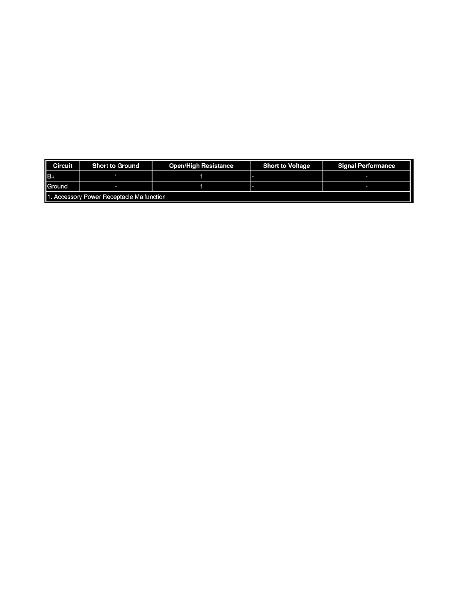
Diagnostic Fault Information
Circuit/System Description
The accessory power receptacles are supplied B+ all the time.
Reference Information
Schematic Reference
Cigar Lighter/Power Outlet Schematics (See: Diagrams/Electrical Diagrams)
Connector End View Reference
Component Connector End Views (See: Diagrams/Connector Views/Connector End Views By Name)
Description and Operation
Power Outlets Description and Operation (See: Description and Operation)
Electrical Information Reference
*
Circuit Testing (See: Testing and Inspection/Component Tests and General Diagnostics/General Electrical Diagnostic Procedures/Circuit
Testing/Circuit Testing)
*
Connector Repairs (See: Testing and Inspection/Component Tests and General Diagnostics/General Electrical Diagnostic Procedures/Connector
Repairs/Connector Repairs)
*
Testing for Intermittent Conditions and Poor Connections (See: Testing and Inspection/Component Tests and General Diagnostics/General
Electrical Diagnostic Procedures/Circuit Testing/Testing for Intermittent Conditions and Poor Connections)
*
Wiring Repairs (See: Testing and Inspection/Component Tests and General Diagnostics/General Electrical Diagnostic Procedures/Wiring
Repairs/Wiring Repairs)
Circuit/System Testing
1. Ignition OFF, disconnect the harness connector at the appropriate X80 accessory power receptacle.
2. Test for less than 5 ohm between the ground circuit terminal C and ground.
‹› If greater than the specified range, test the ground circuit for an open/high resistance.
3. Verify that a test lamp illuminate between the B+ circuit terminal A and ground.
‹› If the test lamp does not illuminate, test the B+ circuit for a short to ground or an open/high resistance.
4. If all circuits test normal, test or replace the X80 accessory power receptacle.
Repair Instructions
Perform the Diagnostic Repair Verification (See: Powertrain Management/Computers and Control Systems/Testing and Inspection/Diagnostic Trouble
Code Tests and Associated Procedures/Verification Tests and Procedures) after completing the diagnostic procedure.