
Suburban 3/4 Ton 4WD V8-305 5.0L (1986)
Antilock Brakes / Traction Control Systems: Service and Repair
ELECTRONIC CONTROL UNIT (ECU)
Do not touch electrical connections and pins or allow them to come into contact with brake fluid.
1.
Disconnect battery ground cable.
2.
Disconnect electrical connectors from ECU.
3.
Pry up tab at rear of ECU and remove unit toward front of vehicle.
4.
Slide unit into bracket until tab locks into hole.
5.
Inspect electrical connectors for brake fluid contamination, clean with alcohol as needed, then connect electrical connectors to ECU.
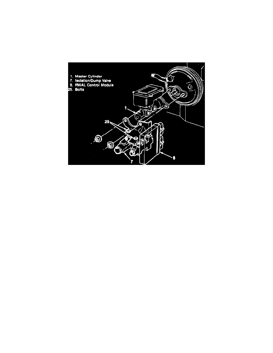
Fig. 46 ECU & Control Valve Assembly Installation
ISOLATION/DUMP VALVE ASSEMBLY
1.
Disconnect brake lines from control valve, the plug lines and open fittings.
2.
Remove bolts (25) securing control valve, Fig. 2, and support valve assembly. Do nor allow valve assembly to hang from wiring.
3.
Disconnect electrical connectors and remove control valve assembly.
4.
Reverse procedure to install, then bleed brakes as needed.
SPEED SENSOR
Speed sensor resistance should be 90---2000 ohms. The sensor is not serviceable, and should be replaced if defective. The speed sensor is located in
the left rear of the transmission for 2 wheel drive models, or on the transfer case for 4 wheel drive models. On some models with 4 speed manual
transmissions (RPO M20), it may be necessary to remove the transmission rear bearing retainer in order to replace the speed sensor.
1.
Raise and support vehicle, then disconnect electrical connector from speed sensor.
2.
On 2 wheel drive models except models with M20 transmission, remove bolt securing speed sensor retainer. On models with M20 transmission
and 4 wheel drive models, loosen sensor with suitable wrench.
3.
Position suitable container under sensor, then remove sensor and O-ring.
4.
Coat O-ring with transmission fluid, then install O-ring and speed sensor.
5.
Torque retainer bolt to 8 ft. lbs. for models with automatic transmission or 9 ft. lbs. for models with manual transmission. On models with M20
transmission and 4 wheel drive models, torque sensor to 32 ft. lbs.
SPEEDOMETER CALIBRATION
The speedometer must be recalibrated to allow proper system operation whenever the rear axle ratio or rear tire size is changed. Calibration requires
the use of a speedometer calibration service kit. When servicing the digital ratio adapter and calibrating the speedometer, do not touch the pins on the
rear of the instrument cluster as immediate damage to the cluster will occur.