
Suburban 3/4 Ton 4WD V8-305 5.0L (1986)
Intake Manifold: Service and Repair
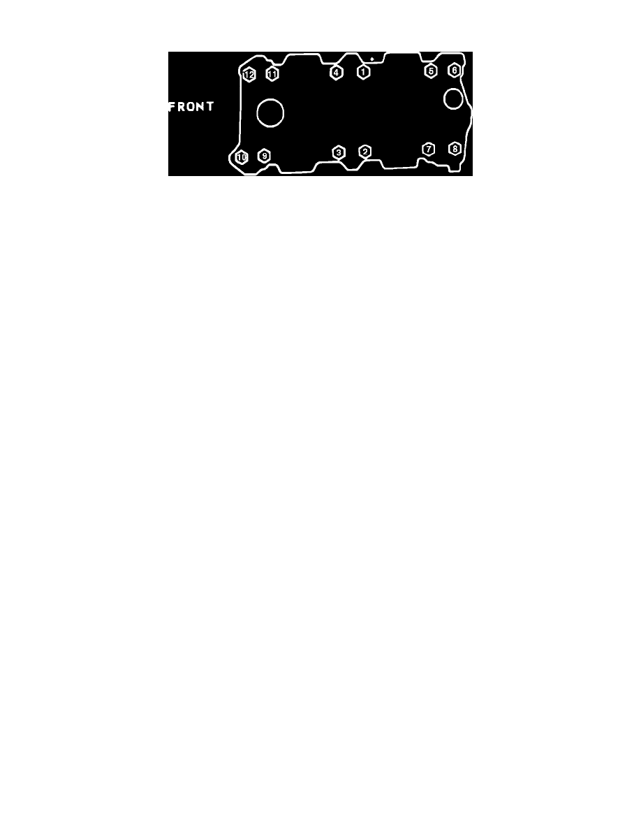
Fig.11 Intake Manifold Tightening Sequence V8-267, 305, 350, 400
Series 10---30/1500---3500
1.
Disconnect battery ground cable, then drain cooling system.
2.
Remove air cleaner.
3.
On G models, remove engine cover.
4.
Remove AIR crossover hose, if applicable.
5.
Disconnect heater and radiator hoses, then remove upper alternator bracket.
6.
Disconnect all vacuum hoses and electrical connections that will interfere with manifold removal.
7.
Disconnect fuel line, linkage and cables from carburetor or TBI unit.
8.
Remove spark plug wires, if necessary.
9.
Remove distributor.
10.
On all except G models with fuel injected engine, if equipped with A/C, remove compressor and bracket and position aside.
11.
On fuel injected models, disconnect ignition coil wires, then remove emission control sensors and bracket on right side. Remove cruise control
transducer and bracket, then the fuel line bracket at rear of manifold. On G models, remove bracket at rear of belt idler.
12.
On all models, remove carburetor or TBI unit, if necessary.
13.
Remove intake manifold attaching bolts, then the intake manifold.
14.
Reverse procedure to install, using new gaskets and seals. Coat front and rear ridges of cylinder case with a 3/16 inch bead of RTV sealant. Extend
bead 1/2 inch up each cylinder head to retain side gaskets, then seal around all water passages. Torque manifold bolts to specification in sequence
shown in Fig. 11.