
Suburban 3/4 Ton 4WD V8-305 5.0L (1986)
Throttle Position Sensor: Adjustments
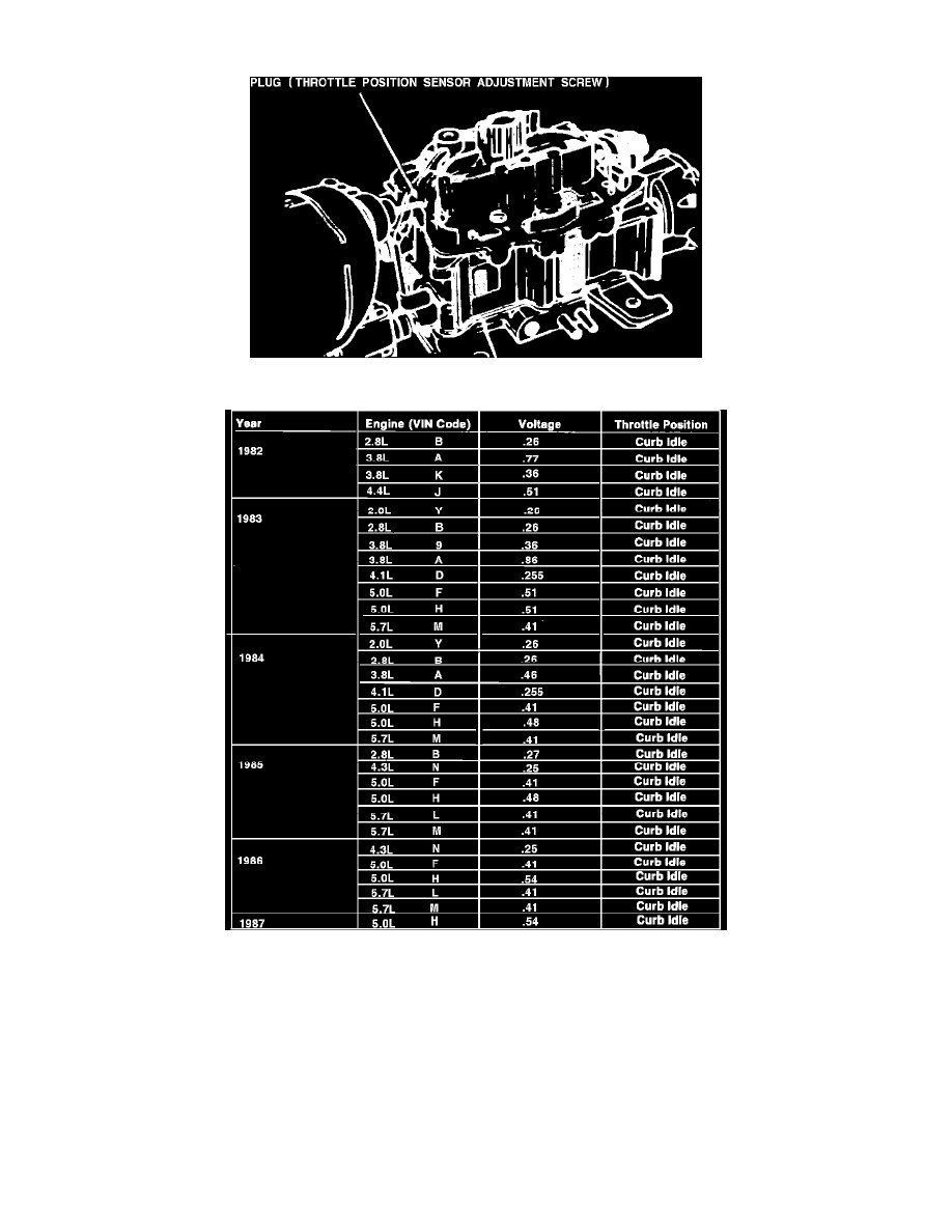
Fig. 15 Throttle Position Sensor Adjustment Screw Cover Removal
Fig. 16 Throttle Position Sensor Specifications
Do not remove plug sealing TPS adjustment or adjust TPS unless carburetor is overhauled or ``Computer Command Control (C3)'' system
diagnosis indicates a problem with the switch.
1.
Drill a .078 (5/64) inch hole, 1/16-1/8 inch deep, in plug covering TPS adjustment,
Fig. 15.
2.
Thread a No. 8 sheet metal screw into hole and pry out plug using a suitable lever.
3.
Remove TPS adjusting screw using tool J-28696 or equivalent.
4.
Leaving electrical connector in place, connect a digital voltmeter between TPS center terminal (B) and bottom terminal (C), using jumper wires if
necessary. Only a digital voltmeter with 10 megohm input impedance or higher can be used. Conventional voltmeters do not have sufficient
resistance to obtain accurate readings.
5.
With ignition on, engine stopped and A/C off, install TPS screw and adjust quickly to obtain specified TPS idle voltage,
Fig. 16.
6.
Turn ignition off and install new plug over TPS adjusting screw or seal opening with RTV sealer.