
Suburban 3/4 Ton 4WD V8-305 5.0L (1986)
Choke Thermostat/Heater: Testing and Inspection
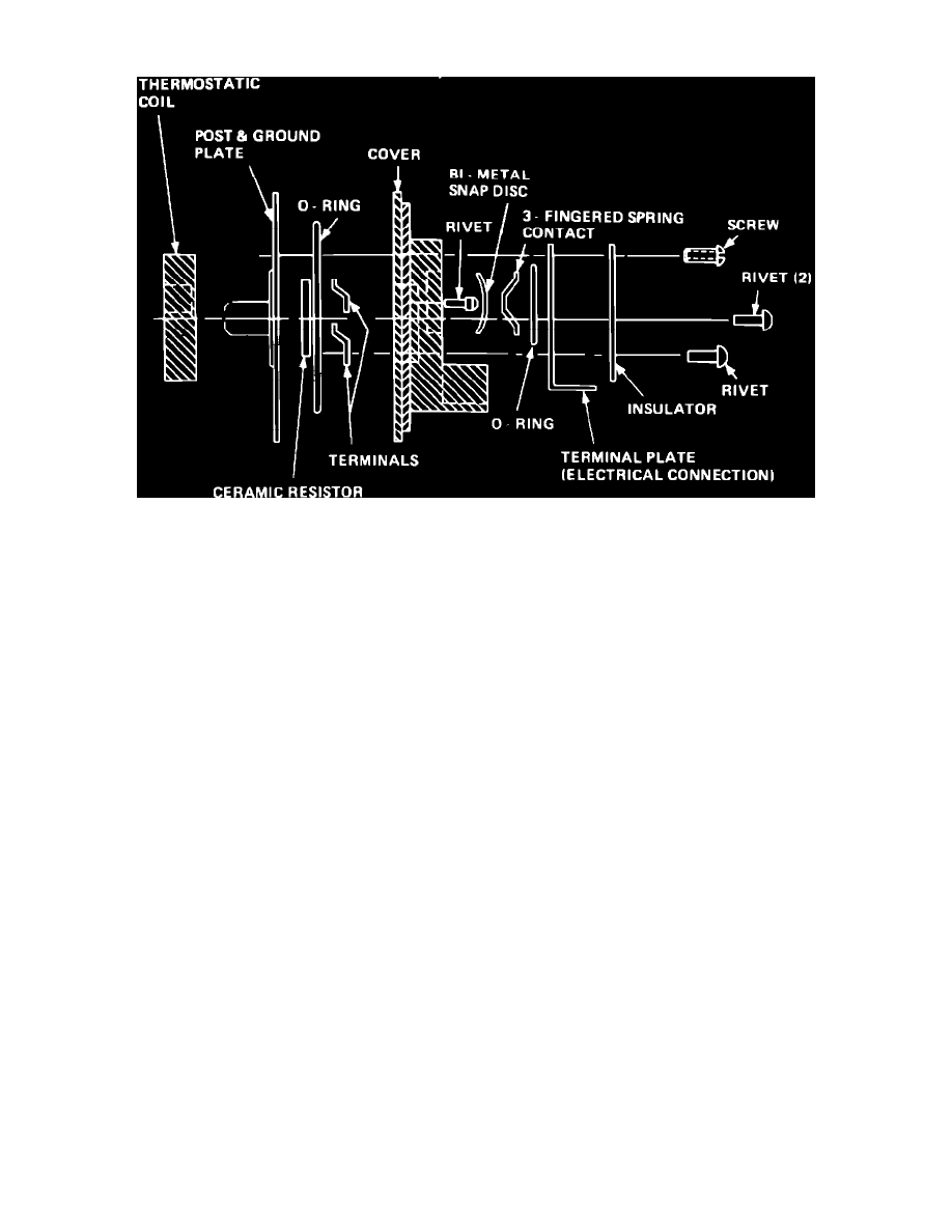
Electric choke assembly exploded view
On most vehicles, an electric assist choke is incorporated onto the carburetor to aid in reducing the emissions of hydrocarbons (HC) and carbon
monoxide (CO) during starting and warm-up (choke-on) period. The electric assist choke is designed to give a more rapid choke opening at temperatures
of approximately 60-65° F., or greater and a slower choke opening at temperatures of approximately 60-65° F., or below. The electric assist choke
system does not change any carburetor service procedures and cannot be adjusted. If the system is out of calibration, the heater control switch and/or
choke unit must be replaced.
The main components of the electric assist choke system, Fig. 39, consist of a thermostatic coil, ceramic resistor, cover, bi-metal snap disc and contact
spring. The electric actuated ceramic resistor heats the thermostatic coil, gradually relaxing coil tension and allowing the choke valve to open.
At air temperatures below 50° F., electric current applied to the small section of the ceramic resistor, allows slow opening of the choke valve for good
engine warm-up. As the small section of the ceramic resistor continues to heat, a bi-metal disc causes the spring loaded contact to close and apply
electric current to the large section of the ceramic resistor which increases the heat flow to the thermostatic coil for more rapid opening of the choke
valve.
At air temperatures between 50-70° F., electric current applied to the small section, or both the small and large sections of the ceramic resistor, will
produce the amount of heat required to control the choke valve position for good engine operation in these temperature ranges.
At air temperatures above 70° F., electric current applied to the small section of the ceramic resistor and through the spring contact to the large section
of the ceramic resistor, provides rapid heating of the thermostatic coil for quicker choke valve opening when leaner air-fuel mixtures are required at
warmer temperatures.
Diagnosis & Testing
Possible conditions for the electric choke not operating properly are listed as follows (use a voltmeter to check oil pressure and choke coil circuits):
1.
Low or no engine oil pressure.
2.
Faulty oil pressure switch.
3.
No current to oil pressure switch due to:
a. Burned out fuse.
b. Broken wire to oil pressure switch.
4.
No current between choke and oil pressure switch due to:
a. Broken lead wire.
b. Wire terminal not properly secured on coil terminal.
c. Faulty ground circuit between choke assembly and housing grounding plate.
5.
Faulty choke coil assembly.
If it is determined that the choke coil assembly is inoperative, the following test must be made:
1.
Remove choke coil from carburetor. After removal of choke coil, allow coil to cool to room temperature.
2.
Connect a ``jumper'' wire between positive battery terminal and choke coil terminal assembly. Connect a second ``jumper'' wire between negative
battery terminal and choke coil assembly grounding plate.
3.
The tang on the choke coil should rotate 45° in 54-90 seconds.
4.
If choke coil does not rotate or exceeds the 54-90 second time limit, replace choke coil.
5.
If coil is within specification, check steps 1 thru 5 for possible cause.