
Suburban 3/4 Ton 4WD V8-305 5.0L (1986)
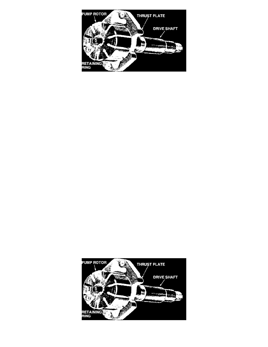
Fig. 4 Thrust plate & rotor installed on driveshaft
1.
Referring to Fig. 1, carefully mount pump in vise with soft jaws and remove reservoir cap. When clamping pump in vise, do not exert excessive
force on front hub as this may distort drive shaft bushing in housing.
2.
Remove rear pump mounting stud and O-ring seal, pressure union and O-ring seal.
3.
Remove reservoir, and second pressure union O-ring seal.
4.
Using a small punch, depress end plate retaining ring enough to allow removal from groove. Use the 1/8 inch diameter hole in housing, Fig. 2.
Then remove retaining ring with screwdriver.
5.
Remove end plate which is spring loaded and usually sits above housing level. If end plate sticks, a slight rocking action should free it. If rocking
action fails to free plate, use a magnet.
6.
Remove two pressure springs from pump housing.
7.
Remove flow control valve and spring by inverting housing. Do not disassemble flow control valve as it is serviced as a unit and pre-set at the
factory, Fig. 3.
8.
Remove drive shaft key from slot in shaft. Then with end of shaft pointed downward, press down until shaft is free.
9.
Turn assembly over and remove drive shaft and rotary group.
10.
Remove rotor retaining ring from groove in drive shaft. Remove rotor and thrust plate from shaft, Fig. 4.
11.
Remove and discard O-ring seals from pump housing. Remove driveshaft oil seal only if inspection shows necessity for replacement.
Inspection
1.
Clean all parts except the drive shaft oil seal in cleaning fluid. The seal will be damaged if immersed in cleaning fluid.
2.
Check fit of vanes in slots of rotor for tightness or excessive looseness. Vanes must fit snugly but slide freely in slots in rotor. Tight fit of vanes in
rotor can usually be corrected by thorough cleaning. Replace rotor if excessive looseness exists between rotor and vanes. Replace vanes if worn or
scored.
3.
Examine machined surfaces of pump ring for roughness or wear. Replace ring if roughness cannot be corrected with crocus cloth.
4.
Inspect thrust plate, pressure plate and end plate for wear, scores or other damage.
5.
Inspect pump housing for cracks or damage. Check housing for evidence of wear or scoring.
6.
Check all springs for free length, distortion or collapsed coils.
7.
Inspect located dowel pins for distortion.
8.
Examine outer diameter of flow control valve for scoring or roughness. Slight damage may be cleaned up with crocus cloth. Check valve assembly
for freedom of movement in bore of pump housing.
9.
Check all oil passages in pump parts for obstruction. Use a piece of tag wire to clean out holes.
10.
Check bushing in pump housing for wear or damage.
Assembly
Fig. 4 Thrust plate & rotor installed on driveshaft