
Suburban 3/4 Ton 4WD V8-305 5.0L (1986)
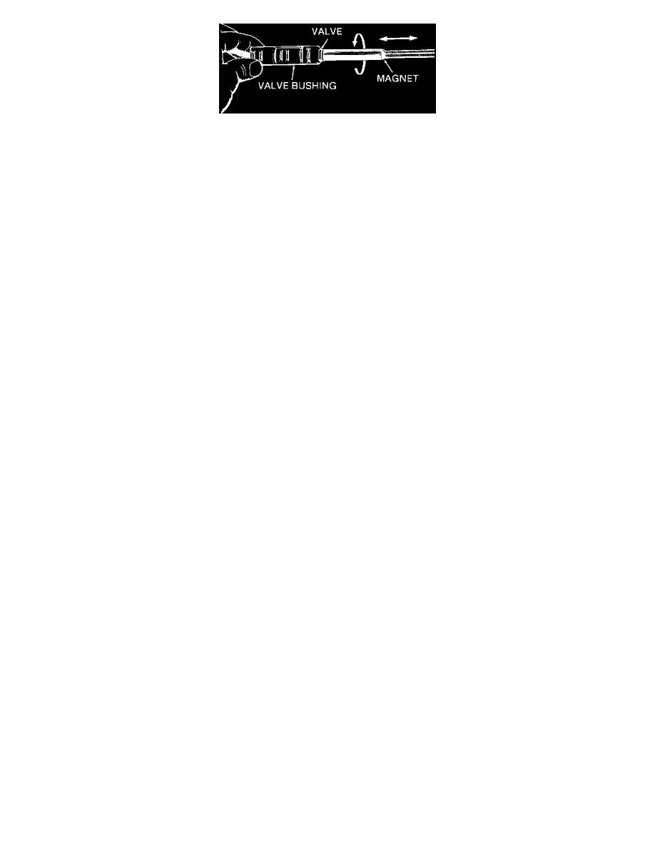
Figure No. 5
2.
A. Steel Valves
^
Using a pencil type magnet, rotate the valve while moving it back and forth in the bore. (Refer to Figure No. 5)
B.
Aluminum Valves
^
Using a small flat blade screwdriver, move the valve back and forth in the bore.
IMPORTANT:
Too much "lapping" of a valve will cause excessive clearances and increase the chance of a valve not operating. Clearances between a
valve and it's sleeve or bore are normally .028- .04 mm (.001-.0015").
3.
After lapping a steel valve with a magnet check for magnetism in the valve by holding it near some steel fillings or chips. If the valve
can pick up the fillings, you must demagnitize it by using a "demagnetizing" tool (different types are available at most tool stores).
4.
Again check the valve for magnetism, and if necessary, demagnetize it following the procedure in step #3. Repeat this procedure until the
magnetism has been removed.
5.
Thoroughly clean the valve and bushing (or bore in the valve body) with solvent and dry using compressed air.
6.
Place the valve in its bushing (or bore in the valve body) and check for freeness of movement by rocking the bushing (or valve body) back
and forth. The valve should travel freely in its bore. If the valve still tends to stick, repeat the lapping procedure.
NOTE:
The use of a honing stone, fine sandpaper or crocus cloth is not recommended for servicing stuck valves. All valve lands have sharply
machined comers that are necessary for "cleaning" the bore. If these corners are rounded, foreign material could wedge between the valve and
bore causing the valve to stick.
REASSEMBLY
1.
Make sure the valve body casting, valves and bushings are completely dry and free of cleaning solvent.
2.
Lubricate all springs, valves and bushings with clean transmission fluid.
3.
Reassemble the valve trains in the valve body casting and check for freedom of movement using a small screwdriver or awl.
4.
Install the control valve assembly into the transmission following procedures as outlined in the appropriate Service Manual.
5.
Tighten the control valve assembly to case attaching bolts by starting from the center of the control valve assembly and moving outward.
IMPORTANT:
Control valve assembly to case attaching bolts must be hand torqued to the specifications given in the appropriate Service Manual.
Improper torque can cause a control valve assembly to not operate properly.