
Suburban 3/4 Ton 4WD V8-305 5.0L (1986)
Differential Clutch: Service and Repair
10 1/2 Inch Ring Gear
Cam Gear Clutch
Fig. 6 Cam Gear Thrust Ring Removal. Eaton Locking Differential
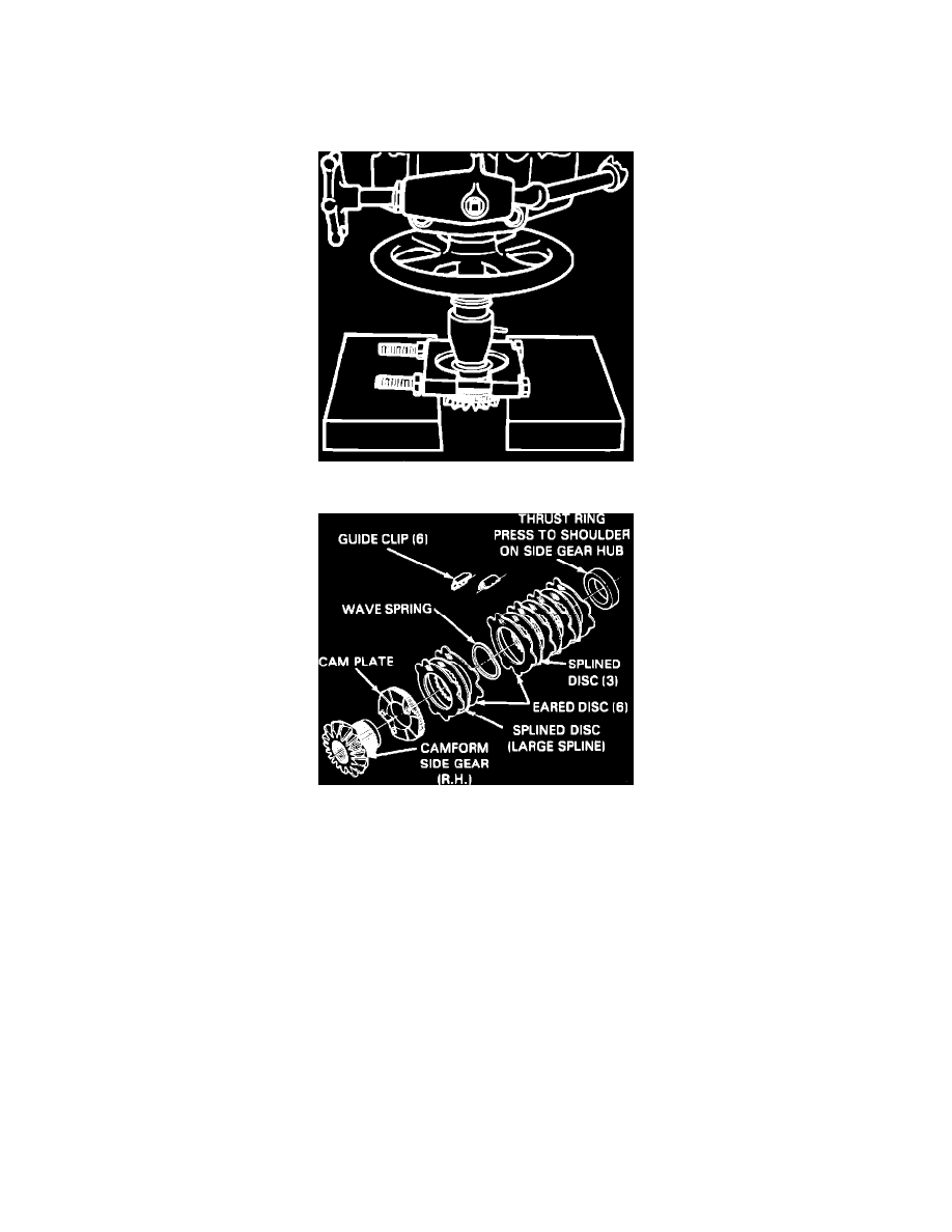
Fig. 4 Exploded View Of Cam Gear Assembly. Eaton Locking Differential
1.
Measure and record overall length of cam gear assembly from front face of gear to back face of thrust ring, including shim.
2.
Compress disc pack and insert jaws of bearing separator tool No. J-22912 or equivalent between thrust ring and top clutch disc with chamfer of
separator facing thrust ring.
3.
Support separator in press and press cam gear from thrust ring using suitable spacer, Fig. 3, keeping components in order as cam gear is removed.
4.
Remove discs, spring and cam plate from gear, Fig. 4, clean and inspect components and replace any that are damaged or excessively worn. Do
not replace cam gear and/or thrust ring unless necessary. If ring or gear is excessively worn or scored, inspect bore in case. If case bore is
scored, differential assembly must be replaced. If cam gear or thrust ring is replaced, shim thickness must be selected to provide original
assembly dimension and proper differential pinion backlash.
5.
Position cam gear with hub facing up and install cam plate with cam form down to mesh with form on gear.
6.
Assemble two eared discs and one disc with large splines on cam plate, starting with eared disc as shown in Fig. 4, then install wave spring. If
components are reused, they must be installed in original position.
7.
Assemble four eared discs and three splined discs on cam gear, starting with eared disc as shown in Fig. 4.
8.
Position cam gear assembly in press and install thrust ring on hub of gear, ensuring that ring is square with hub.
9.
Compress disc pack to prevent disc from being trapped, then press thrust ring onto cam gear until ring is seated against shoulder of gear.
10.
Inspect assembly and ensure that components are properly installed.
Side Gear (LH) Clutch