
Suburban 3/4 Ton 4WD V8-305 5.0L (1986)
4.
Install new pinion seal in housing, coat seal lips with grease, then mount driveshaft yoke on pinion shaft, lightly tapping yoke until several pinion
shaft threads protrude from yoke.
5.
Coat rear of pinion washer with suitable sealer, then install washer and new pinion nut.
6.
Hold driveshaft yoke with suitable tool, then alternately tighten pinion nut and rotate pinion until endplay is reduced to zero.
7.
When endplay is reduced to zero, check pinion bearing preload using a torque wrench.
8.
Continue tightening pinion nut in small increments until 35-40 inch lbs. of bearing preload is obtained with new bearings or 20-25 inch lbs. of
bearing preload is obtained with used bearings, rotating pinion and checking preload after each adjustment.
Exceeding preload specification will
compress collapsible spacer too far, requiring replacement of spacer. If preload specification is exceeded, spacer must be replaced and
adjustment procedure must be repeated. Do not loosen pinion nut to reduce preload.
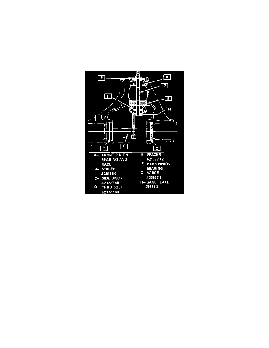
4 - Pinion
Fig. 5 Drive pinion & bearing shim adjustment
1.
Install front pinion bearing cup in carrier using tool J-7817 or equivalent.
2.
Install spacer (E) into carrier bore,
Fig. 5.
3.
Slide rear pinion bearing and cap (F) onto thru bolt (D) and rear bearing into axle housing.
4.
Install thru bolt (D), rear bearing and cap (F) into axle housing.
5.
Assemble front bearing cone (A) and spacer (B) onto thru bolt.
6.
Rotate nut and shaft while increasing torque on nut until a rotational
torque of 15-22 inch lbs. is obtained. Rotate thru bolt back and forth when
tightening nut to properly seat bearing.
7.
Install discs on thru bolt assembly as shown in
Fig. 5. Position carrier so dial indicator contact rod is directly over gauging area of gauge plate
J-35118-2.
Discs must be fully seated in side bearing bores.
8.
Install bearing caps over gauge shaft discs, then the cap attaching bolts.
torque attaching bolts to 40 ft. lbs.
9.
With dial indicator rod contacting gauging area of J-35118-2, rock gauge shaft back and forth until dial indicator measures the greatest deflection,
then zero dial indicator.
10.
Rotate gauge shaft until shaft does not contact gauge plate, then note measurement.
11.
Select correct pinion shim as follows:
a. If reusing production pinion, and pinion is marked with a ``+,'' correct shim will have a thickness equal to gauge reading minus amount
specified on pinion.
b. If reusing production pinion, and pinion is marked with a `` - ,'' correct shim will have a thickness equal to gauge reading plus amount specified
on pinion.
c. If using a production or service pinion which has no marking, correct shim will have a thickness equal to gauge reading.
12.
Install selected pinion shim into carrier, then press rear pinion bearing cup into carrier using tool J-5590 or equivalent.
13.
Press rear pinion bearing onto pinion using a bearing installation tool, then install pinion in carrier.
14.
Install collapsible spacer and front bearing onto pinion while supporting pinion under head.
15.
Install oil seal, companion flange and new nut on pinion, then tighten pinion nut until a rotating
torque of 10-25 inch lbs. with new bearings or
5-12 inch lbs. with original bearings is obtained while rotating pinion forwards to seat bearings.
16.
If preload is excessive after tightening pinion nut, replace collapsible spacer and repeat steps 14 and 15.