
Suburban 3/4 Ton 4WD V8-305 5.0L (1986)
Universal Joint: Service and Repair
Double Cardan Type
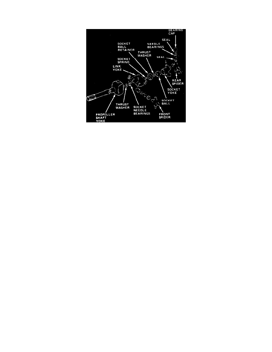
Fig. 9 Double cardan universal joint exploded view
The double cardan type joint, Fig. 9, incorporates two universal joints, a centering socket yoke, and center yoke at one end of the shaft. A single
universal joint is used at the other end.
DISASSEMBLY
1.
Remove all bearing cap retainers.
2.
Mark bearing caps, spiders, propeller shaft yoke, link yoke and socket yoke for assembly alignment reference, Fig. 9.
3.
Remove bearing caps attaching from spider to propeller shaft yoke as follows:
a. Use a 5/8 inch socket to drive the bearing cap and a 1-1/16 inch socket to receive the opposite bearing cap as it is driven out.
b. Place 5/8 inch socket on one bearing cap and 1-1/16 inch socket on opposite bearing.
c. Position assembly in vise so vise jaws bear directly against sockets.
d. Tighten vise to press first bearing cap out of link yoke.
e. Loosen vise, reposition sockets and press opposite bearing cap out of link yoke.
4.
Disengage propeller shaft yoke from link yoke.
5.
Remove bearing caps attaching front spider to propeller shaft as described in step 3 above.
6.
Remove front spider from yoke.
7.
Remove bearing caps attaching rear spider to link yoke as outlined in step 3 above and remove spider and socket yoke from link yoke.
8.
Clean all parts in solvent and wipe dry. Inspect assembly for damage or wear. If any component is worn or damaged, the entire assembly must be
replaced.
ASSEMBLY
When assembling universal joint, make sure to align spiders and yokes according to marks made during disassembly.
1.
Lubricate all bearings and contact surfaces with lithium base chassis grease.
2.
Install bearing caps on yoke ends of rear spider and secure caps with tape, Fig. 9.
3.
Assemble socket yoke and rear spider.
4.
Position rear spider in link yoke and install bearing caps. Press caps into yoke using 5/8 inch socket until bearing cap retainer grooves are exposed.
5.
Install rear spider-to-link yoke bearing cap retainers.
6.
Position front spider in propeller shaft yoke and install bearing caps. Press caps into yoke using a 5/8 inch socket until bearing cap retainer grooves
are exposed.
7.
Install front spider-to-propeller shaft yoke bearing cap retainers.
8.
Install thrust washer and socket spring in ball socket bearing bore, if removed.
9.
Install thrust washer on ball socket bearing boss (located on propeller shaft yoke), if removed.
10.
Align ball socket bearing boss on propeller shaft yoke with ball socket bearing bore and insert boss into bore.
11.
Align front spider with link yoke bearing cap bores and install bearing caps. Press caps into yoke using a 5/8 inch socket until bearing cap retainer
grooves are exposed.
12.
Install front spider-to-link yoke bearing cap retainers.