
Accord L4-1751cc 1800 EK1 (1982)
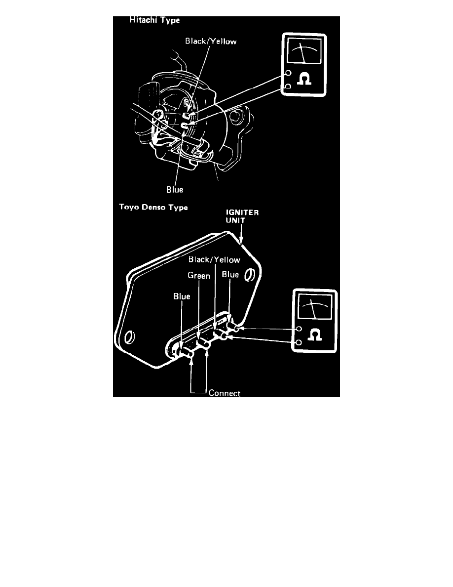
Fig. 2 Igniter Unit Continuity Test Connections.
1.
Disconnect lead wires from igniter unit.
2.
Check voltage between blue wire and ground, then between black/yellow wire and ground with ignition switch in ON position, Fig. 1. Battery
voltage should be present.
3.
Check continuity between igniter unit terminals using an ohmmeter, Fig. 2. Continuity should be present with ohmmeter positive probe to
black/yellow wire terminal and negative probe to blue wire terminal. Continuity should not be present with ohmmeter positive probe to blue wire
terminal and negative probe to black/yellow wire terminal.