
Accord L4-1955cc 2.0L SOHC 2-bbl (1986)
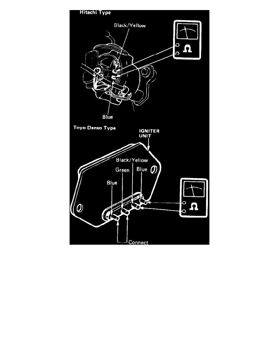
Fig. 2 Igniter Unit Continuity Test Connections.
EXC. 1985-88 CIVIC/CIVIC WAGON & CRX & 1988 PRELUDE
1.
On models with Hitachi distributor, disconnect lead wires from igniter unit. On models with Toyo Denso distributor, remove igniter cover and pull
out igniter unit.
2.
Check voltage between blue wire and ground, then between black/yellow wire and ground with ignition switch in ON position, Fig. 1. Battery
voltage should be present. On models with Toyo Denso distributor, two blue wires are used. Be sure to perform voltage check on blue wire
indicated in Fig. 1.
3.
If battery voltage is not present at either wire, trace circuit and repair as needed.
4.
Measure resistance between green terminal and other blue terminal on pickup coil. If resistance is not approximately 750 ohms at 70°F, replace
pickup coil.
5.
Check continuity between igniter unit terminals shown in Fig. 2, connecting ohmmeter leads in both directions. Continuity should be present in
one direction only.
6.
If continuity is indicated in both directions or if continuity is not indicated in either direction, igniter is defective.
7.
Connect ohmmeter positive probe to blue terminal and negative probe to ground, then measure resistance on igniter input. Resistance should be at
least 50,000 ohms at 70°F.