
Accord L4-2156cc 2.2L SOHC (1991)
4 Of 4
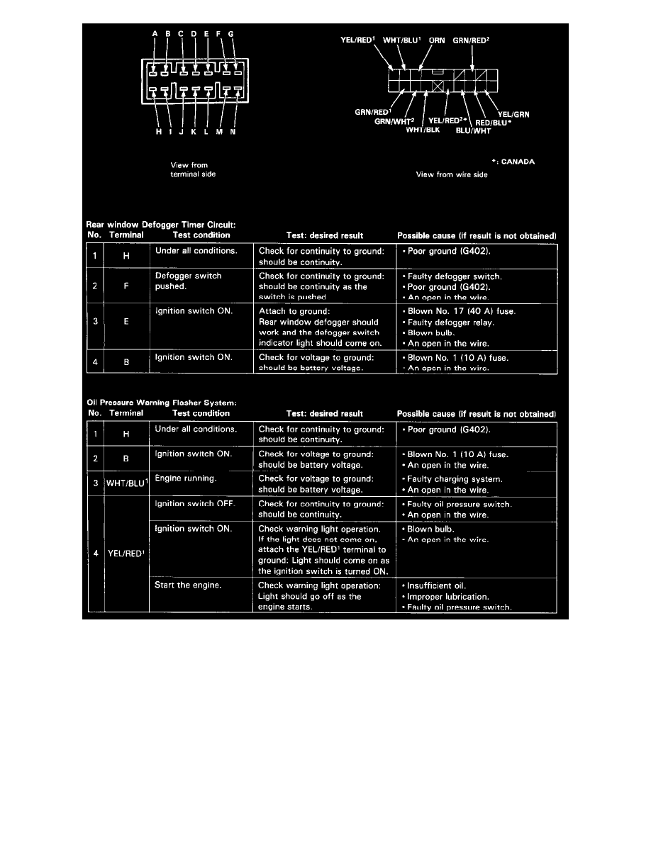
Remove the left side kick panel cover, then disconnect the 16-P connector from the integrated control unit. Remove the integrated control unit from the
dash fuse box.
Make the illustrated input tests at the harness pins. If all tests prove OK, yet the system still fails to work, replace the control unit.
NOTE:
^
Several different wires have the same color. They have been given a number suffix to distinguish them (for example BLU/WHT1 and BLU/WHT2
are not the same).
^
Do not disconnect all of the connectors on the dash fuse box except the integrated control unit.