
Accord LX Sedan V6-3.0L (2001)
Distinct Of Circuit By Wire Base Color
All wires have color-coded insulation.
Wires belonging to a system's main harness will have a single color. Wires belonging to a system's sub-circuits will have a colored stripe. Striped wires
use the codes found in the chart to show wire size and colors.
Abbreviations are used to indicate wire color within a circuit diagram.
How to Identify Connector Terminals
How to Identify Connector Terminals
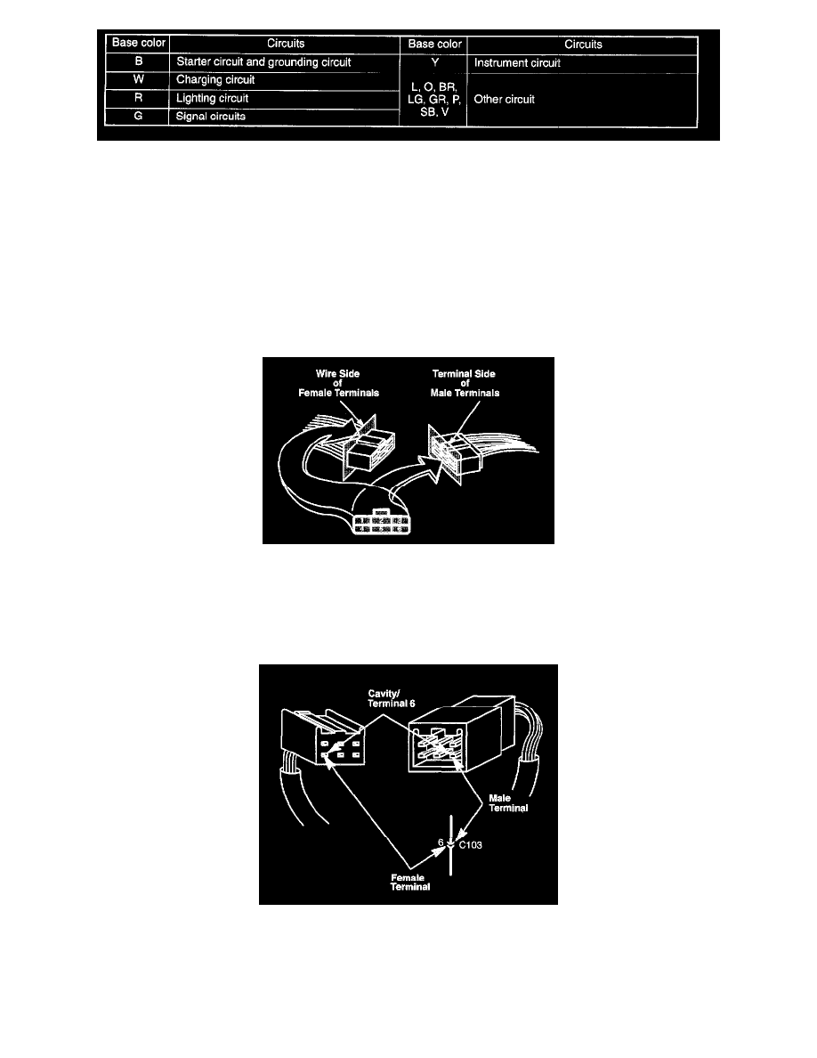
Cavity Numbering System
The cavities (and wire terminals) in each connector are numbered starting from the upper left, looking at the male terminals from the terminal side (or
looking at the female terminals from the wire side. Both views are in the same direction so the numbers are the same.) All actual cavities are numbered,
even if they have no wire terminals in them.
NOTE: Data Link Connector (DLC) terminals are numbered according to SAE standard J1962, not the Honda standard. The numbers of the four end
terminals are molded into the corners of the connector face.
The connector cavity number is listed next to each terminal on the circuit schematic. The cavity / terminal shown is # 6.
Using/Identifying Connector Terminal Views
How to Use Connector Terminal Views
To see the configuration of a connector's cavities, look up its view number in the Connector Views. Each view includes the color of the connector, where