
Prelude L4-1958cc SOHC (1988)
Voltage Regulator: Testing and Inspection
Prior to performing test, check for proper alternator belt tension and proper electrical connections at alternator. Also check battery condition and for
blown fuses at fuse panel and engine compartment relay panel.
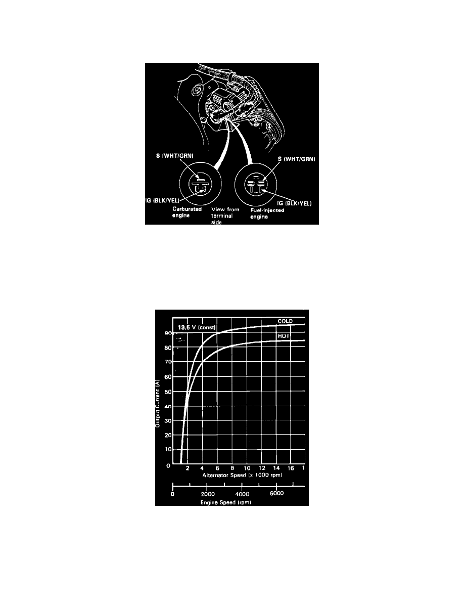
Fig. 4 Alternator Electrical Connector Pin Identification. 1989-91 Prelude
1.
Disconnect electrical connector from alternator.
2.
With ignition switch in the On position, check for battery voltage between ground and alternator connector terminals IG and S. If battery voltage is
indicated at both terminals, proceed to step 3. If no voltage is indicated, check for the following:
a. Check for blown fuse in fuse panel.
b. Check for open circuit in wiring (black/yellow wire) between fuse panel and voltage regulator.
c. Check for open circuit in wiring (white/green wire) between engine compartment relay panel and voltage regulator.
Fig. 9 Alternator current output chart. 1988 Prelude
3.
To further test the alternator and regulate Sun Vat 40 or other suitable charging system tester should be used. Follow tester manufacturer's
instructions for test connections and settings. When performing alternator and regulator tests with tester note the following:
a. When checking alternator output, operate engine at 2000 RPM with engine cooling fan off. Apply a load to charging system so that voltage
drops to no lower than 12 volts. Tester readings should be within 10 amps of the readings indicated in. If readings are within specification,
the charging system is operating properly, refer to ``Charge Warning Lamp Test.'' If readings are not within specification, proceed to step b.