
Prelude L4-2.3L DOHC (1992)
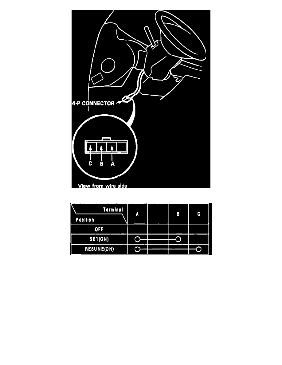
Fig. 41 Set/Resume Switch Connector Identification
Fig. 42 Set/Resume Test
1.
Disarm coded theft protection system, if equipped, as described under
MAINTENANCE PROCEDURES/CODED THEFT PROTECTION
DISARMING.
2.
Remove dashpanel lower cover, then disconnect combination light switch 4-P connector from main wire harness,
Fig. 41.
3.
Check for continuity between terminals of set/resume switch according to table shown in
Fig. 42.
4.
If continuity is as described in table, set/resume switch is functioning properly.
5.
If no continuity exists, or continuity exists only in some positions, remove steering wheel and repeat step 3 using the 4-P connector of the steering
wheel.
6.
If there is no continuity in any switch position, replace the set/resume switch.
7.
If there is continuity in every switch position, check for the following conditions:
a. Faulty slip ring.
b. An open circuit in combination switch wires between A and A', B and B' or C and C'.