
Ridgeline V6-3.5L (2006)
connectors on the under-dash fuse/relay box.
-
If any test indicates a problem, find and correct the cause, then recheck the system.
-
If all the input tests prove OK, go to step 6.
Gauge Control Module
6. Turn the ignition switch OFF.
7. Remove the gauge control module.
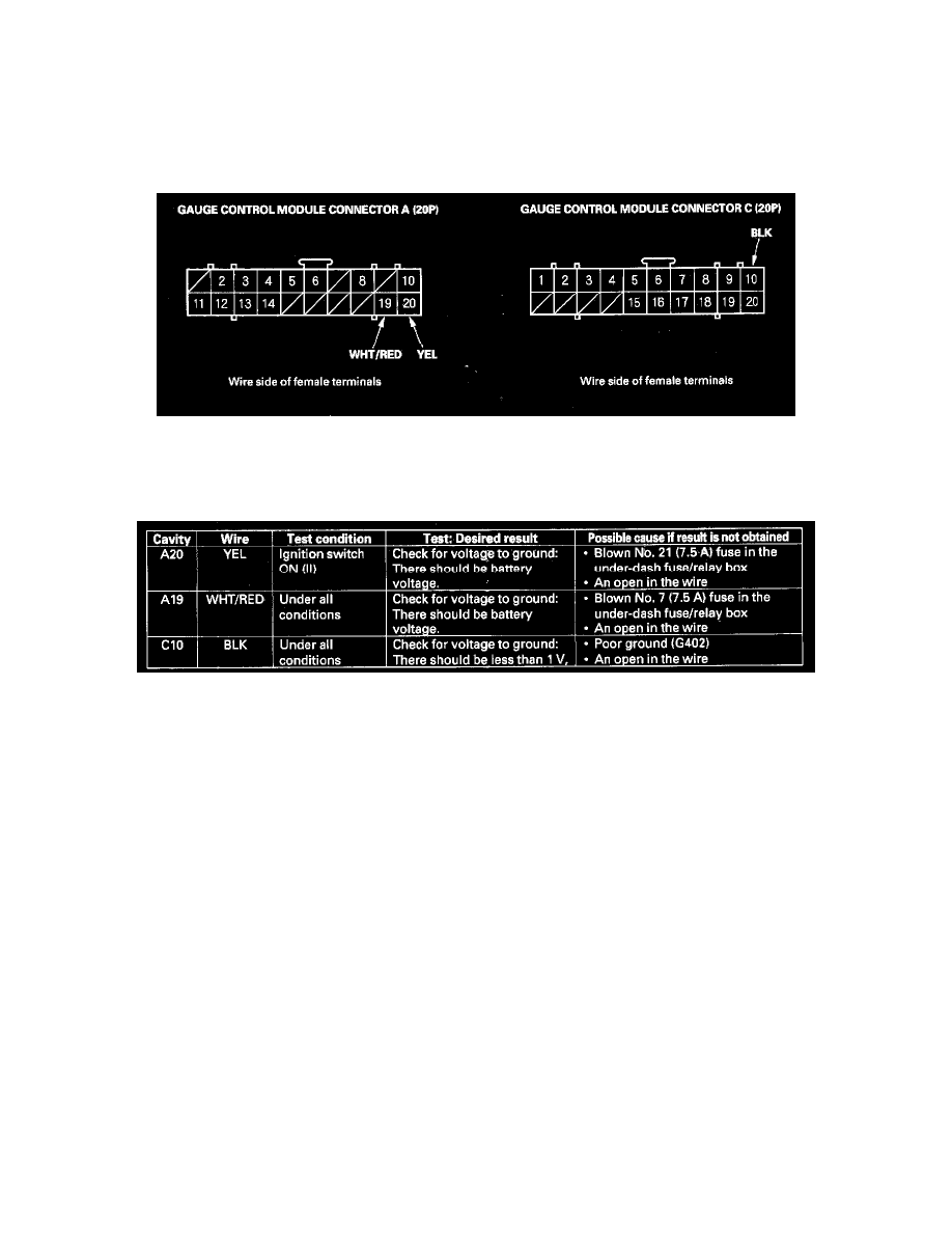
8. Disconnect the gauge control module connectors A (20P) and C (20P).
9. Inspect the connector and socket terminals to be sure they are all making good contact.
-
If the terminals are bent, loose or corroded, repair them as necessary, and recheck the system.
-
If the terminals look OK, go to step 10.
10. Reconnect the connectors to the gauge control module, turn the ignition switch ON (II), and make these input tests at the connector.
-
If any test indicates a problem, find and correct the cause, then recheck the system.
-
If all the input tests prove OK, go to step 11.
11. If all the input tests prove OK, and no DTCs were found during MICS troubleshooting (B-CAN System Diagnostic Test Mode A), go to the
B-CAN system input and output index. See: Powertrain Management/Computers and Control Systems/Information Bus/Testing and
Inspection/Initial Inspection and Diagnostic Overview/System Description If multiple failures are found on more than one control unit, replace the
under-dash fuse/relay box (includes the MICU). If input failures are related to particular control unit, replace the control unit.