
Accent GS Coupe L4-1495cc 1.5L SOHC MFI (1999)
Crankshaft Position Sensor: Diagnostic Aids
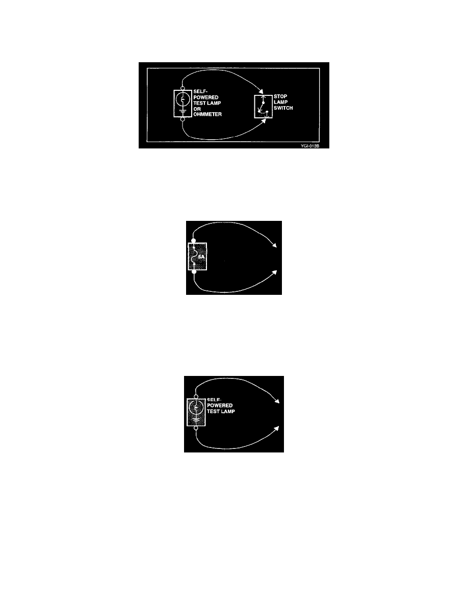
Continuity and Voltage Test
1. Disconnect the battery negative terminal.
2. Connect one lead of a self powered test lamp or ohmmeter to one end of the part of the circuit you wish to test. If you are using an ohmmeter, hold
the leads together and adjust the ohmmeter to read zero Ohms.
3. Connect the other lead to the other end.
4. If the self-powered test lamp glows, there is continuity. If you are using an ohmmeter, low or zero resistance means good continuity.
Jumper Wire With Fuse
Use a jumper wire with fuse to by pass an open circuit.
A jumper wire is made up of an in-line fuse holder connected to a set of test leads. This tool is available with small clamp connectors providing adaption
to most of the connectors without damage.
CAUTION: Do not use a fuse with a higher rating then the specified fuse that protests the circuit being tested. Do not use this tool in any situation to
substitute for input or output at the solid-state control module, such as ECM, TCM, etc.
Self-Powered Test Lamp and Ohmmeter
Use a self powered test lamp or a ohmmeter to check for continuity. Self-powered test lamp is made of a bulb, battery and two leads are touched
together, the lamp will go on. Prior to checking the points, first disconnect the battery ground cable or remove the fuse which feeds the circuit you are
working on.
CAUTION:
Never use a self-powered test lamp on circuits that contain solid state modules. Damage to these units may result.
An ohmmeter can be used in place of a self-powered test lamp. The ohmmeter shows how much resistance there is between two points along a circuit.
Low resistance means good continuity.
Circuits which include any solid-state devices should be tested only with at 10 Mega Ohm or higher impedance digital multimeter. When measuring
resistance with a digital multimeter, battery negative terminal should be disconnected. Otherwise, there may be incorrect readings. Diodes and solid-state
devices in a circuit can make an ohmmeter give a false reading. To find out if a component is affecting a measurement, take one reading, reverse the