
Elantra L4-1595cc 1.6L DOHC (1993)
3. Or, if there is no continuity when a 50 kPa (70 psi) vacuum is applied through the oil hole, the switch is operating properly. Check to see that air
doesn't leak. If air leaks, the diaphragm Is broken. Replace the switch.
Oil Pump
1. Assemble the oil pump gear to the front case and rotate it to ensure smooth rotation with no looseness.
2. Ensure that there is no ridge wear on the contact surface between the front case and gear surface of the oil pump cover.
Fig. 12 Measuring Oil Pump Gear Tip Clearance
3. with the drive and driven gears installed into the front case, measure the tip clearance of the gears.
[Standard value]
Drive gear
0.16-0.21 mm (0.0063-0.0083 in.)
Driven gear
0.13-0.18 mm (0.0051-0.0071 in.)
[Limit]
Drive gear
0.25 mm (0.0098 in.)
Driven gear
0.25 mm (0.0098 in.)
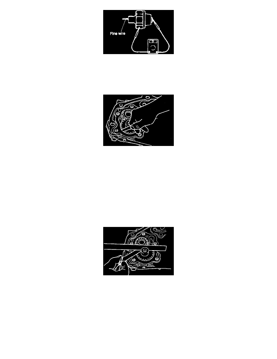
Fig. 13 Measuring Oil Pump Gear Side Clearance
4. Check the side clearance.
[Standard value]
Drive gear
0.08-0.14 mm (0.0031-0.0055 in.)
Driven gear
0.06-0.12 mm (0.0024-0.0047 in.)
[Limit]
Drive gear
0.25 mm (0.0098 in.)
Driven gear