
Sonata V6-2.7L (2004)
NOTE: The pin guide should be centered on the connecting rod through the piston. If assembled correctly, the pin guide will sit exactly under the
center of the hole in the tool's arch, and rest evenly on the fork inserts. If the wrong size pin guide is used, the piston and pin will not up with the
support fixture.
7. Insert the installer tool through the hole in the arch of the support fixture and use an hydraulic press to force the piston pin through the rod little
end. Continue pressing until the pin guide falls free and the installer tool seats against the top of the arch.
CAUTION: Do not exceed 1250 - 500 kgf (2765 - 1100 lbs.) of force when the installing tool seats against file top of the arch.
INSPECTION
PISTONS AND PISTON PINS
1. Check each piston for scuffing, scoring, wear and other defects. Replace any piston that is defective.
2. Check each piston ring for breakage, damage and abnormal wear. Replace the defective rings. When the piston requires replacement, its rings
should also be replaced.
3. Check that the piston pin fits in the piston pin hole. Replace any piston and pin assembly that is defective. The piston pin must be pressed
smoothly by hand into the pin hole (at room temperature).
PISTON RINGS
1. Measure the piston ring side clearance. If the measured value exceeds the service limit, insert a new ring in the ring groove to measure the side
clearance. If the clearance still exceeds the service limit, replace the piston and rings together. If it is less than the service limit, replace only the
piston rings.
Piston ring side clearance
No.1: 0.04 - 0.08 mm (0.0016 - 0.0031 inch)
No.2: 0.03 - 0.07 mm (0.0012 - 0.0028 inch)
[Limit]
No.1: 0.1 mm (0.004 inch)
No.2: 0.1 mm (0.004 inch)
2. To measure the piston ring end gap, insert a piston ring into the cylinder bore. Position the ring at right angles to the cylinder wall by gently
pressing it down with a piston. Measure the gap with a feeler gauge. If the gap exceeds the service limit, replace the piston ring.
Piston ring end gap
Standard dimensions]
No.1: 0.20 - 0.35 mm (0.0079 - 0.0138 inch)
No.2: 0.37 - 0.52 mm (0.0146 - 0.0205 inch)
[Limit]
No.1, No.2: 0.8 mm (0.031 inch)
Oil ring side rail: 1.0 mm (0.039 inch)
When replacing the ring without correcting the cylinder bore, check the gap with the ring situated at the lower part of cylinder that is less worn out.
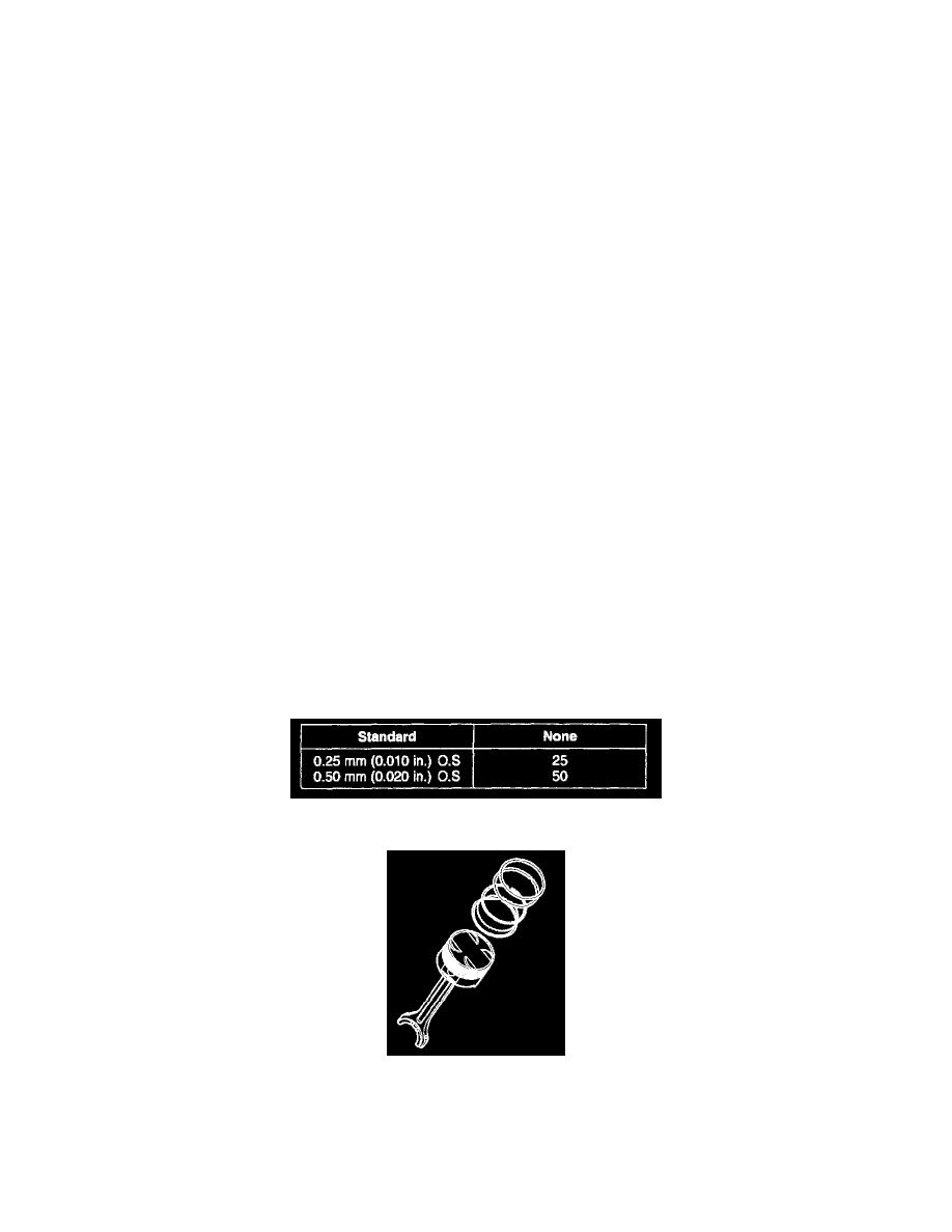
PISTON RING SERVICE SIZE AND MARK
NOTE: The mark can be found on the upper side of the ring next to the end.
CONNECTING RODS
1. When the connecting rod cap is installed, make sure that the cylinder numbers, marked on rod end cap at disassembly, match. When a new
connecting rod is installed, make sure that the notches holding the bearing in place are on the same side.