
Sonata V6-3.0L (1991)
Oxygen Sensor: Testing and Inspection
***UPDATED BY TSB# ENG016, APRIL, 1989
NOTE: In the event of a recurring check engine light accompanied by an oxygen sensor fault code, the probable cause is a poor alternator to engine
ground, and excessive resistance in the battery ground circuit. For the recommended correction refer to TSB# ENG016.
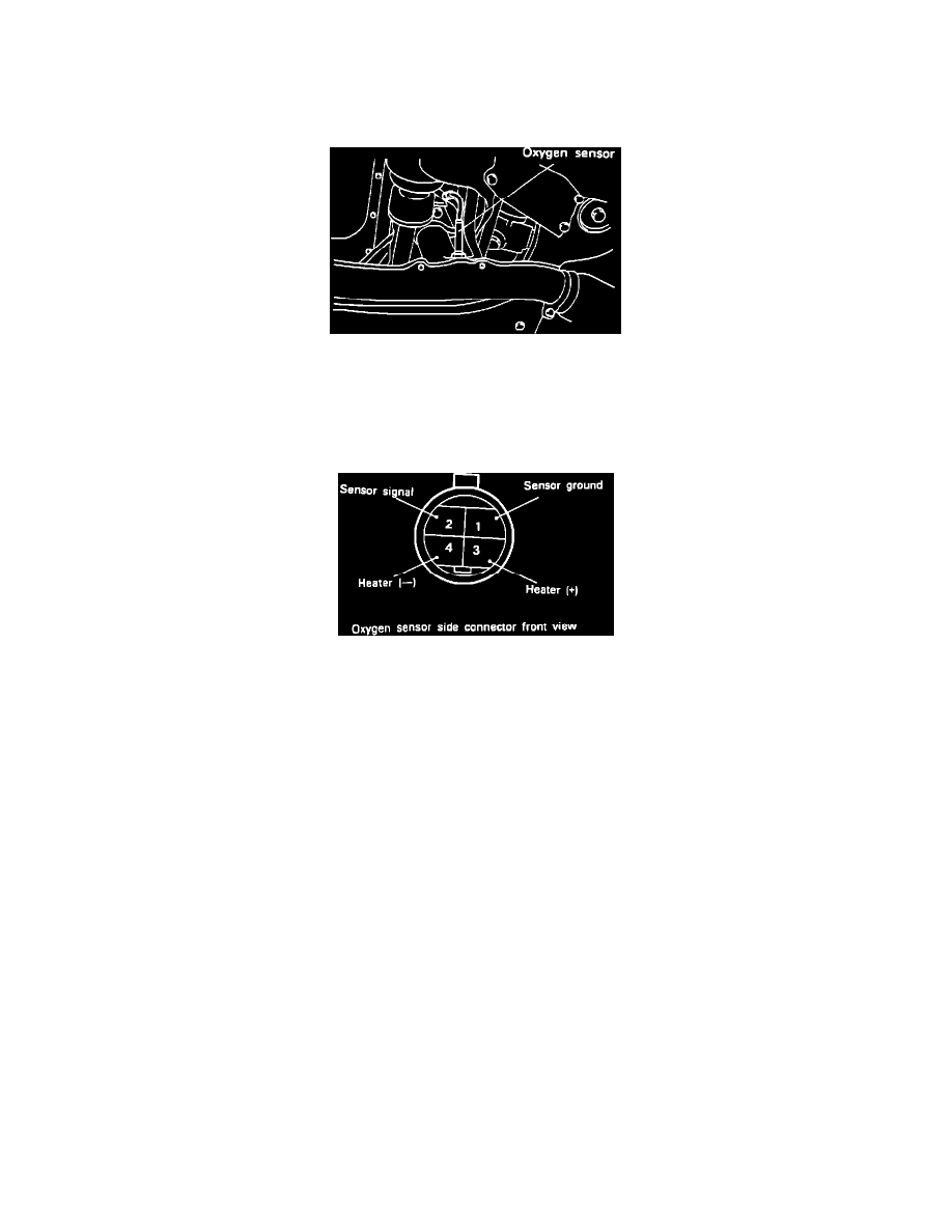
Oxygen Sensor Location
To test the Oxygen Sensor, located on the exhaust manifold, proceed as follows.
SENSOR OUTPUT TEST:
1.
Start the engine and allow it to reach operating temperature.
Oxygen Sensor Connector Identification
2.
Disconnect the oxygen sensor from the wire harness and connect a digital voltmeter (greater than 1 Meg ohm input impedance) between the oxygen
sensor output connector and ground (terminals #1 and #2).
3.
Increase engine rpm to approximately 1,500 rpm.
4.
After approximately 70 seconds of operation at elevated rpm measure the output voltage of the oxygen sensor while changing engine rpm up and
down slightly.
5.
A properly operating oxygen sensor voltage signal should fluctuate between approximately 0.1 vdc and 0.9 vdc.
6.
If voltage output is low or non-existent replace the oxygen sensor.
HEATER TEST:
7.
Disconnect the oxygen sensor connector and measure the resistance between terminal 3 and terminal 4.
Standard Value...30 or more ohms @752~ or more
Replace the oxygen sensor if it doesn't meet the specification.