
Sonata V6-3.0L (1991)
Distributor: Description and Operation
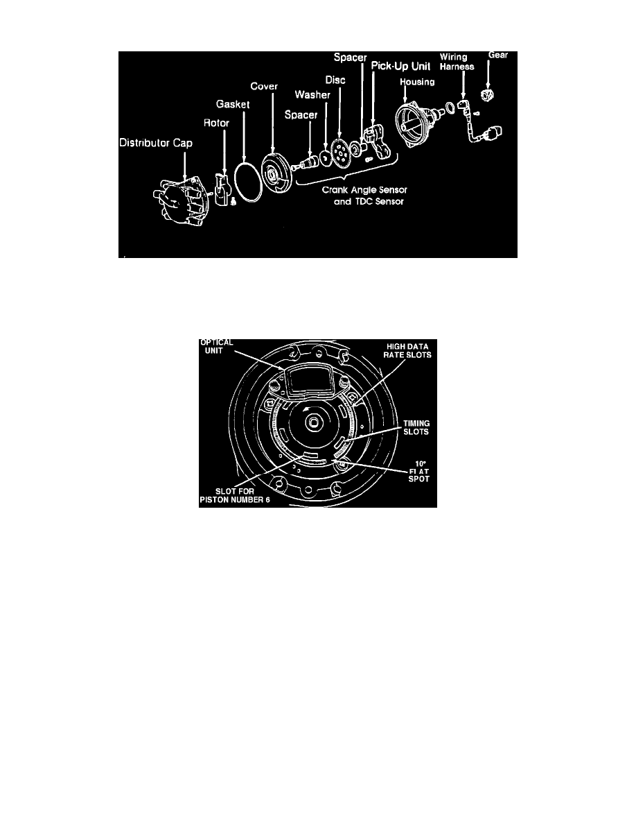
Distributor Exploded View
The Distributor consists of a housing, shaft, drive gear, distributor cap and rotor, and houses the crankshaft angle and the No.1 cylinder TDC sensors.
The drive gear (mounted on the end of the distributor shaft) drives the shaft at cam shaft speed. On the other end of the shaft the rotor is mounted. When
properly timed the rotor carries current from the coil tower in the distributor cap to the correct spark plug electrode for the designated firing order.
Crank Angle And #1 TDC Sensor
The crankshaft angle sensor and the No.1 cylinder TDC sensor are composed of a disc and unit assembly. The disc is a metal disc which has six
light-transmission slits located 60° apart around its circumference. There is also an additional series of slits (1° per slit at 2° increments, with a 10° blank
space) located on the outer circumference of the disc. The inner slits are for the crankshaft angle sensor (individual cylinder timing referance marks). The
outer series of slits is to establish No.1 TDC.
The disc is affixed to the distributor shaft. When the shaft rotates, the slits in the disc are optically read by the unit assembly. The unit assembly, in order
to be able to detect the two types of slits, incorporates two luminous diodes and two photo diodes. There is a very slight clearance between the luminous
diodes and the photo diodes, and the disc rotates within this space.