
Tucson AWD L4-2.4L (2010)
-
Each Diagram is consisted of circuits by system. This schematic diagram includes the path of electricity flow, connection condition for each
switch, and the function of other relevant circuits at once. It is applicable to real service work.
-
It is very important to understand relevant circuits exactly before troubleshooting diagnosis.
-
Circuits by system depends upon part number and are indicated on schematic diagram index.
2
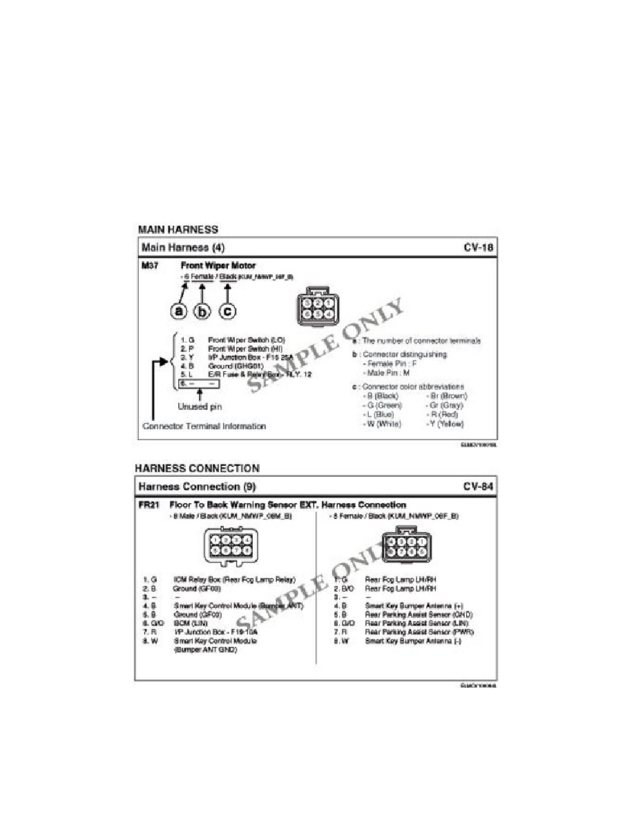
Connector Views
i.
This section shows followings.
-
Figure of the front view of the connector (harness side, not component side)
-
Color of the connector
-
Number of the terminal
-
Color of the wiring
-
Function of the terminal
ii. Each terminal on the connector is numbered in accordance with (3) Connector View And Numbering Order.
iii. Not connected terminal is marked with a dash (-).
iv. For example:
3. Connector View And Numbering Order