
Veracruz FWD V6-3.8L (2009)
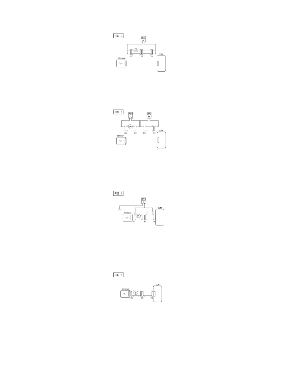
In [FIG.2.] the measured resistance of line 1 and 2 is higher than 1MOhms and below 1 Ohms respectively. Specifically the open circuit is line
1 (Line 2 is normal). To find exact break point, check sub line of line 1 as described in next step.
B. Disconnect connector (B), and measure for resistance between connector (C) and (B1) and between (B2) and (A) as shown in [FIG. 3].
In this case the measured resistance between connector (C) and (B1) is higher than 1MOhms and the open circuit is between terminal 1 of
connector (C) and terminal 1 of connector (B1).
3. Voltage Check Method
A. With each connector still connected, measure the voltage between the chassis ground and terminal 1 of each connectors (A), (B) and (C) as
shown in [FIG. 4].
The measured voltage of each connector is 5V, 5V and 0V respectively. So the open circuit is between connector (C) and (B).
Check Short Circuit
1. Test Method for Short to Ground Circuit
A. Continuity Check with Chassis Ground
If short to ground circuit occurs as shown in [FIG. 5], the broken point can be found by performing Step 2 (Continuity Check Method with Chassis
Ground) as shown below.
2. Continuity Check Method (with Chassis Ground)
NOTE:
Lightly shake the wire harness above and below, or from side to side when measuring the resistance.
Specification (Resistance)