
Majestic L6-4.0L (1990)
ABS Control Module: Description and Operation
ELECTRONIC CONTROL MODULE
The control module processes the signals from the four wheel sensors, converts their frequency information into values which correspond to wheel
speed and then, with the data received, controls the solenoid valves during braking under ABS control.
The control module checks the inputs and output signals in order to indicate a ABS disturbances, a self-monitoring function is integrated in the control
module and a ABS warning lamp is illuminated in the case of a system failure.
During ABS control, the respective solenoid valves in the wheel circuit concerned is controlled. The main valve is controlled when a front wheel is
under ABS control. In order to enable the wheel to transmit the optimum brake force under all road conditions, the control of the valves must be
operate very rapidly, up to 6 times a second.
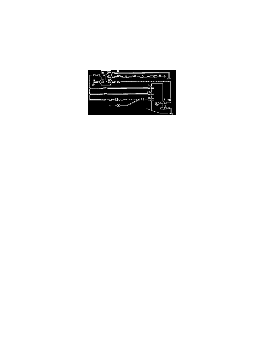
Wiring Diagram
When the ignition is switched on, battery voltage is supplied to pin 2 of the control module which is fed internally to pin 8. From pin 8, the main relay
coil is activated closing the relay contacts. Battery voltage is supplied to pins 3 and 20 of the control module via a 30 amp fuse and the relay contacts,
which switches the electronic control module on to start its test routines.
During the test routines, the ABS warning lamp is illuminated. The time the lamp is illuminated depends on the charging of the hydraulic
accumulator. During this testing phase the electronic control module switches the warning lamp from pin 27 to pin 1 of the control module to ground.
If the system test routines prove satisfactory the electronic control module opens the ground circuit between pins 1 and 27 of the control module, the
circuit to ground is broken, the warning light is then extinguished. The warning lamp is supplied with battery voltage from the ignition switch when
the ignition is switched on.