
XJ-6 L6-4.2L (1983)
Alignment: Technical Service Bulletins
Tools - Wheel Alignment Setting
ITEM:
J83/30June/July, 1983
SUBJECT:
WHEEL ALIGNMENT SETTING
MODEL:
XJ6, VANDEN PIAS, & XJ-S HE
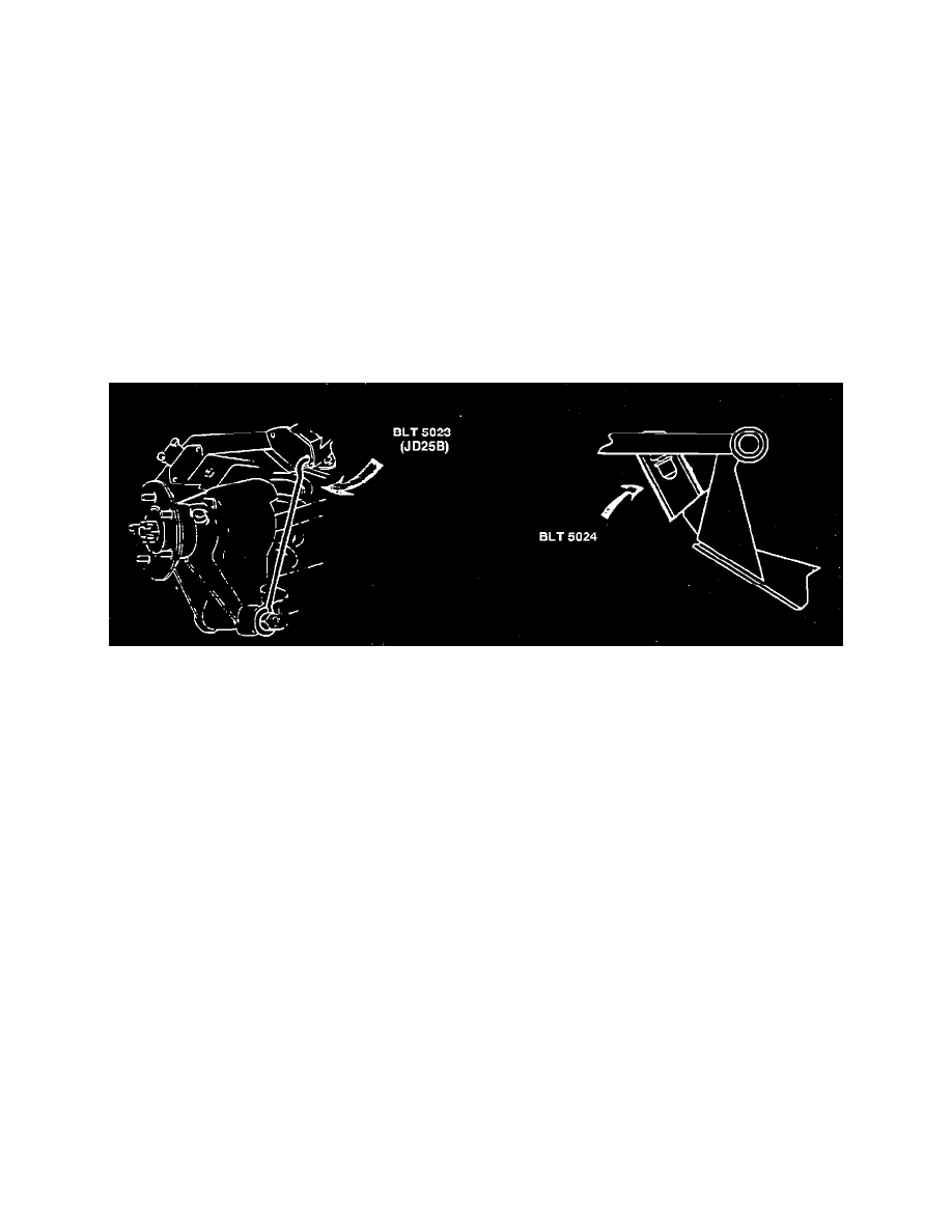
Two special tools to be used when checking and setting wheel alignment will be supplied to each Jaguar dealer.
P/N BLT-5023 (JD25B) are the setting links which hold the rear suspension in the mid-laden position, and P/N BLT-5024 are the spacer tubes for the
front suspension.
Preparing for Castor and Camber Setting
1.
Check all suspension bushes, upper & lower wishbone ball joints and shock absorber mountings for signs of deterioration, damage, or distortion.
2.
Check tire pressures and ensure that the vehicle is on a level surface.
FIGURE 1
3.
Compress the front suspension and insert the setting tubes BLT-5024, over the rebound rubbers with the bottom of the tubes resting on the
rebound flange (see Fig. 1).
4.
Compress rear suspension and hook the suspension links, BLT-5023, through the lower holes of the suspension mounting and over the nut
securing the nut lower pivot pin.
The vehicle is now ready for checking.
Procedures for adjusting castor and camber are contained in the XJ-S Repair Operation Manual 57.65.04 and 57.65.05 and the XJ6 Repair Operation
Manual 57.65.05. The rear camber adjustment is covered in section 64.25.18 in both the XJ-S and XJ6 manuals.
The following wheel alignment settings are applicable to both Series III and VDP sedans and, XJ-S HE models:
Front wheel alignment
-
0-1/8" toe in
Camber angle, front
-
1/2~ Negative + - 1/4~
Camber angle, rear
-
3/4~ Negative + - 1/4~
Castor angle
-
3-1/2~ Positive + 1/4~