
Commander 2WD V6-3.7L (2009)
-
Tire Pressure Monitor System - If Equipped
-
Personal Settings (customer programmable features)
-
Compass display
-
Outside temperature display
-
Trip computer functions
The EVIC system is comprised of several different components. Those components are:
-
Instrument Cluster
-
Steering Wheel Function Buttons
-
Ambient Temperature Sensor
-
Remote Compass Module (RCM)
-
Controller Area Network (CAN) Data Bus
The EVIC display is part of the Instrument Cluster assembly and is not serviced as a separate component. If the display is inoperative the complete
Instrument Cluster assembly must be replaced, See: Instrument Cluster / Carrier/Service and Repair/Removal and Replacement/Instrument Cluster -
Removal. If the EVIC function buttons are inoperative and require replacement, See: Service and Repair/Removal and Replacement/Electronic Vehicle
Information Center - Removal for the appropriate procedure. The RCM is a separate stand alone module mounted to the top side of the headliner. It is
mounted in one of two locations depending on if the vehicle is equipped with CommandView(R) dual fixed second row skylights. If the vehicle is
equipped with CommandView(R) skylights the module is located between the two glass panels. If the vehicle is not equipped with CommandView(R)
skylights the module is located on the left side of the vehicle above the second row seats. If the compass position sensor (Remote Compass Module) is
inoperative and requires replacement,See: Body and Frame/Interior Moulding / Trim/Console/Service and Repair/Overhead Console - Removal for the
appropriate procedure.
Electronic Vehicle Information Center - Operation
OPERATION
The Electronic Vehicle Information Center (EVIC) uses both non-switched and ignition switched sources of battery current so that some of its features
remain operational at any time, while others may only operate with the ignition switch in the On position. When the ignition switch is turned to the On
position, the EVIC display will return to the last function being displayed before the ignition was turned to the Off position.
The EVIC system is comprised of several different components that communicate over the Controller Area Network (CAN) Data Bus. If the system is
inoperative a scan tool and the appropriate diagnostic information must be used to diagnose the system.
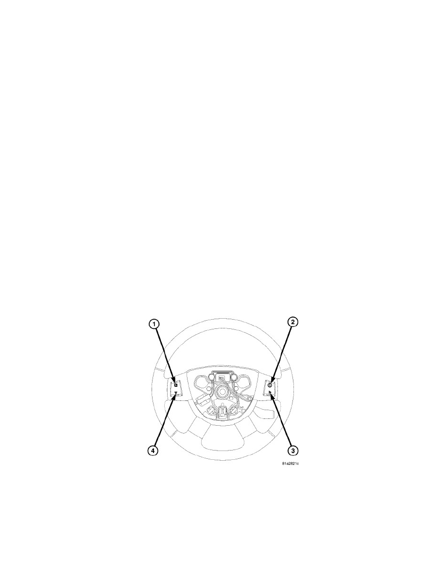
The EVIC function buttons are used to operate the different functions of the EVIC system. Pressing and releasing the MENU button (1) allows the driver
to select the Compass/Temperature, Trip Computer, Personal Settings or System Status functions. The STEP button (4) is used to toggle through options
or features of the Trip Computer, Personal Settings or System Status functions. Pressing and releasing the RESET button (3) allows the selection of
setting or resetting of the function currently displayed at that time. Pressing and releasing the C/T (compass/temperature) button (2) will cause the EVIC
to return to the compass/temperature display mode from any other mode.
EVIC DISPLAY MODES
SYSTEM STATUS MODE