
Commander 2WD V6-3.7L (2009)
bulb test. This output will be interrupted if the system is active and senses an obstacle. Following the conclusion of the bulb test, when the system is
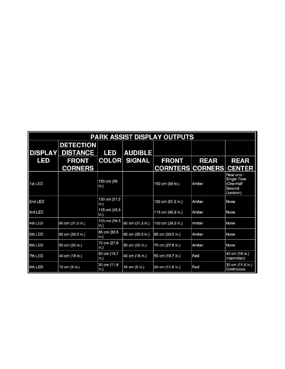
active but no obstacle is detected, the display will indicate system readiness by illuminating the two outermost amber LED units (1) at a reduced
intensity. As an obstacle is detected, the outermost amber LED unit (5) on the side of the vehicle where the obstacle was detected will be illuminated at
normal intensity and, for the rear system only, a single short audible tone (one-half second duration) is sounded. Then additional amber LED units (6)
will begin illuminating inward (2 or 4) as the obstacle gets closer until, finally, the two red LED units (7) are illuminated.
When the final red LED unit (3) is illuminated, the obstacle is approximately 40 centimeters (16 inches) from the front or rear corner of the vehicle or
approximately 50 centimeters (19.7 inches) from the front or rear bumper face and an intermittent audible tone will be generated. The frequency of the
audible tone will increase as the obstacle continues to become closer until the tone is continuous when the obstacle is about 15 centimeters (6 inches)
from the front or rear corner of the vehicle or about 30 centimeters (12 inches) from the front or rear bumper face. Whenever a park assist audible tone is
being generated, the park assist module sends electronic audio mute messages to the radio over the Controller Area Network (CAN) data bus to mute
the audio system. The audible tone will be cancelled after about two seconds if the detected distance to the obstacle remains constant. See the Park Assist
Display Outputs table for additional details.
The hard wired circuits between components related to the park assist display may be diagnosed using conventional diagnostic tools and procedures.
Refer to the appropriate wiring information. The wiring information includes wiring diagrams, proper wire and connector repair procedures, details of
wire harness routing and retention, connector pin-out information and location views for the various wire harness connectors, splices and grounds.
However, conventional diagnostic methods will not prove conclusive in the diagnosis of the park assist display or the electronic controls or
communication between modules and other devices that provide some features of the park assist system. The most reliable, efficient, and accurate means
to diagnose the park assist display or the electronic controls and communication related to park assist display operation requires the use of a diagnostic
scan tool. Refer to the appropriate diagnostic information.
Park Assist Disabled Indicator - Description
DESCRIPTION
A park assist disabled indicator is standard equipment on all instrument clusters. However, on vehicles not equipped with an optional front or rear park
assist system this indicator is electronically disabled. The park assist disabled indication appears within the reconfigurable dot matrix Organic Light
Emitting Diode (OLED) display unit. The park assist disabled indicator consists of a textual PARK ASSIST DISABLED message which appears in
place of the compass/trip computer information in the dot matrix display.
The dot matrix OLED is soldered onto the cluster electronic circuit board, and is visible through a window with a smoked clear lens located on the lower
edge of the tachometer gauge dial face of the cluster overlay. The dark lens over the OLED prevents it from being clearly visible when it is not
illuminated. The PARK ASSIST DISABLED textual message appears in the same white color and at the same lighting level as the compass/trip
computer information when it is illuminated by the instrument cluster electronic circuit board.