
Commander 2WD V6-3.7L VIN K (2006)
Pressure Regulating Solenoid: Description and Operation
SOLENOID
DESCRIPTION
The typical electrical solenoid used in automotive applications is a linear actuator. It is a device that produces motion in a straight line. This straight
line motion can be either forward or backward in direction, and short or long distance.
A solenoid is an electromechanical device that uses a magnetic force to perform work. It consists of a coil of wire, wrapped around a magnetic core
made from steel or iron, and a spring loaded, movable plunger, which performs the work, or straight line motion.
The solenoids used in transmission applications are attached to valves which can be classified as normally open or normally closed. The normally
open solenoid valve is defined as a valve which allows hydraulic flow when no current or voltage is applied to the solenoid. The normally closed
solenoid valve is defined as a valve which does not allow hydraulic flow when no current or voltage is applied to the solenoid. These valves perform
hydraulic control functions for the transmission and must therefore be durable and tolerant of dirt particles. For these reasons, the valves have
hardened steel poppets and ball valves. The solenoids operate the valves directly, which means that the solenoids must have very high outputs to close
the valves against the sizable flow areas and line pressures found in current transmissions. Fast response time is also necessary to ensure accurate
control of the transmission.
The strength of the magnetic field is the primary force that determines the speed of operation in a particular solenoid design. A stronger magnetic field
will cause the plunger to move at a greater speed than a weaker one. There are basically two ways to increase the force of the magnetic field:
1. Increase the amount of current applied to the coil or
2. Increase the number of turns of wire in the coil.
The most common practice is to increase the number of turns by using thin wire that can completely fill the available space within the solenoid
housing. The strength of the spring and the length of the plunger also contribute to the response speed possible by a particular solenoid design.
A solenoid can also be described by the method by which it is controlled. Some of the possibilities include variable force, pulse-width modulated,
constant ON, or duty cycle. The variable force and pulse-width modulated versions utilize similar methods to control the current flow through the
solenoid to position the solenoid plunger at a desired position somewhere between full ON and full OFF. The constant ON and duty cycled versions
control the voltage across the solenoid to allow either full flow or no flow through the solenoid's valve.
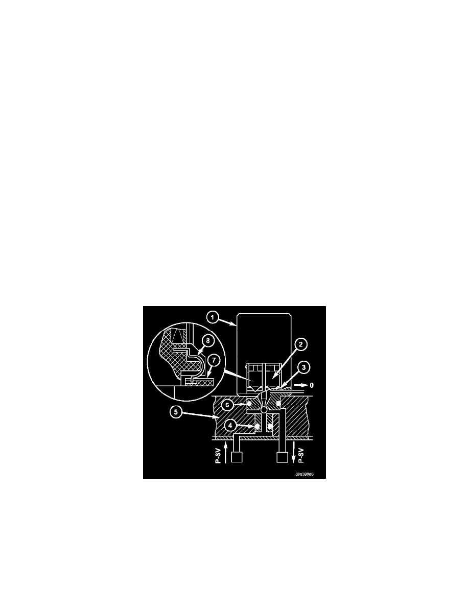
UPSHIFT/DOWNSHIFT SOLENOID VALVES
The solenoid valves (1) for upshifts and downshifts are located in the shell of the electric control unit and pressed against the shift plate with a spring.
The solenoid valves (1) initiate the upshift and downshift procedures in the shift plate.
The solenoid valves (1) are sealed off from the valve housing of the shift plate (5) by two O-rings (4, 6). The contact springs (8) at the solenoid valve
engage in a slot in the conductor tracks (7). The force of the contact spring (8) ensures safe contacts.
MODULATING PRESSURE CONTROL SOLENOID VALVE