
Commander 4WD V8-4.7L VIN N (2006)
Vacuum Brake Booster: Description and Operation
POWER BRAKE BOOSTER
DESCRIPTION
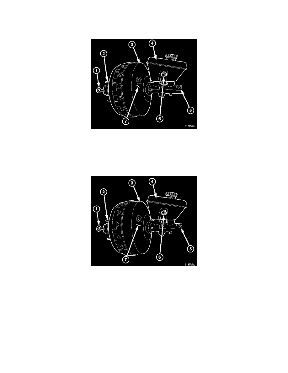
The booster assembly consists of a housing divided into separate chambers by two internal diaphragms. The outer edge of each diaphragm is attached
to the booster housing (3).
Two push rods are used in the booster. The primary push rod (1) connects the booster to the brake pedal. The secondary push rod connects the booster
to the master cylinder to stroke the cylinder pistons.
OPERATION
The atmospheric inlet valve is opened and closed by the primary push rod. Booster vacuum supply is through a hose attached to an intake manifold
fitting at one end and to the booster check valve (7) at the other. The vacuum check valve in the booster housing is a one-way device that prevents
vacuum leak back.
Power assist is generated by utilizing the pressure differential between normal atmospheric pressure and a vacuum. The vacuum needed for booster
operation is taken directly from the engine intake manifold. The entry point for atmospheric pressure is through a filter and inlet valve at the rear of the
housing.
The chamber areas forward of the booster diaphragms are exposed to vacuum from the intake manifold. The chamber areas to the rear of the
diaphragms, are exposed to normal atmospheric pressure of 101.3 kilopascals (14.7 pounds/square inch).
Brake pedal application causes the primary push rod (1) to open the atmospheric inlet valve. This exposes the area behind the diaphragms to
atmospheric pressure. The resulting pressure differential provides the extra apply force for power assist.
The booster check valve, check valve grommet (7) and booster seals are serviceable.