
Commander 4WD V8-4.7L VIN N (2006)
Evaporator Temperature Sensor / Switch: Description and Operation
SENSOR-EVAPORATOR TEMPERATURE
DESCRIPTION
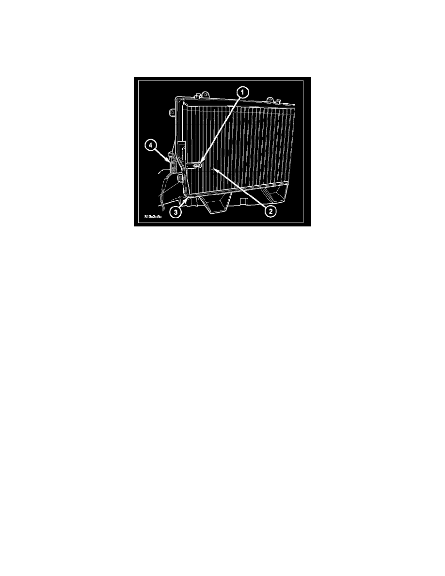
NOTE: LHD model shown. RHD model similar.
The evaporator temperature sensor (1) measures the temperature of the conditioned air downstream of the A/C evaporator (2). The evaporator
temperature sensor is an electrical thermistor within a molded plastic case that is inserted into the HVAC housing (3) near the coldest point of the A/C
evaporator. Two terminals within the connector receptacle (4) connect the sensor to the vehicle electrical system through a wire lead and connector of the
HVAC wire harness.
The external location of the evaporator temperature sensor allows the sensor to be removed or installed without disturbing the refrigerant in the A/C
system.
OPERATION
The evaporator temperature sensor is a thermistor that operates on a 5-volt reference signal sent out by the A/Cheater control. The sensor connects to the
A/C-heater control through a two-wire lead and connector of the HVAC wire harness. The sensor monitors the temperature of the conditioned air
downstream of the A/C evaporator and changes its internal resistance in response to changes in the air temperature. As the temperature increases, the
sensor's resistance decreases which increases the reference signal voltage read by the A/C-heater control. As the temperature decreases, the sensor's
resistance increases which decreases the reference signal voltage read by the A/C-heater control.
The A/C-heater control also uses the reference signal voltage as an indication that conditions are correct to request A/C operation, should the operator
(manually) or the A/C-heater control (automatically) so desire this function. For the ATC system, the A/C-heater control broadcasts the A/C request on
the controller area network (CAN) B bus, where it is read and processed by the front control module (FCM), which in turn broadcasts it on the CAN C
bus, where it is read and processed by the powertrain control module (PCM). For the MTC system, the A/C-heater control sends the request for A/C to
the CCN via a dedicated mux circuit. The CCN then broadcasts the A/C request on the CAN B bus, where it is read and processed by the FCM, which in
turn broadcasts it on the CAN C bus, where it is read and processed by the PCM.
The evaporator temperature sensor is diagnosed using a scan tool.
The evaporator temperature sensor cannot be adjusted or repaired and, if faulty or damaged, it must be replaced.