
Commander 4WD V8-4.7L VIN N (2006)
7.
Shifter Bezel Installation.
a.
**Ensure the solenoid connector is seated in the shifter housing and make sure that the connector pins of the interface in the bezel and the
wiring connector are both upright and aligned prior to shifter bezel installation as shown in (Fig. 2).**
b.
Align the transportation tube onto the top of the shifter lever, lower the new shifter bezel onto the shift lever and discard the tube.
c.
Position the shifter bezel on the shifter housing and connector and install the screws in the bin and at the housing. Torque the screws to 1.5 -
2.1 Nm (13.5 - 18.5 in. lbs.).
d.
If equipped, install the TC switch with two screws from the bottom, torque the screws to 0.89 - 1.11 Nm (7.8 - 9.8 in. lbs.).
e.
Connect the wiring connector to TC switch.
f.
Connect the wiring connector to the shifter bezel.
g.
Ensure cable routing does not interfere with slide guides and slider exit.
8.
Install Shift Knob And Trim Mat.
a.
Verify that shifter is in the neutral position.
b.
Position knob with chrome ring on lever and seat fully.
c.
Turn lower chrome ring of shift knob clockwise 90°.
d.
Place the trim mat into shifter bezel bin.
9.
**Verify the brake transmission shift interlock operation:
a.
Verify that the key can only be removed in the PARK position.
b.
When the shift lever is in PARK, the ignition key cylinder should rotate freely from ACC to LOCK. When the shifter is in any other gear or
neutral position, the ignition key cylinder should not rotate to the LOCK position.
c.
Shifting out of PARK should not be possible when the ignition key cylinder is in the ACC position and the brake pedal is not depressed.
d.
Shifting out of PARK should not be possible while applying normal force on the shift lever and ignition key cylinder is in the ACC, ON, or
START positions unless the foot brake pedal is depressed approximately 12 mm (1/2 in.).
e.
Shifting out of PARK should not be possible when the ignition key cylinder is in the LOCK position, regardless of the brake pedal position.
f.
Shifting between any gears, NEUTRAL or into PARK may be done without depressing foot brake pedal with ignition switch in ACC, ON,
or START positions.**
10.
Install the center floor console using the procedures outlined in TechCONNECT 23 - Body>Interior>Floor Console>Installation.
POLICY:
Reimbursable within the provisions of the warranty.
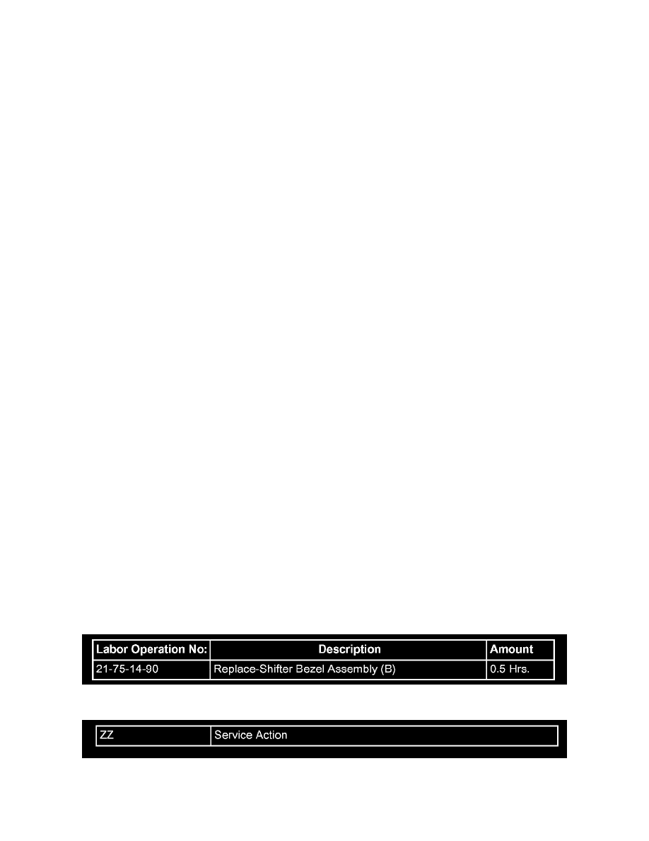
TIME ALLOWANCE:
FAILURE CODE:
Disclaimer: