
Commander 4WD V8-4.7L VIN N (2006)
Brake Light Switch: Description and Operation
SWITCH-STOP LAMP
DESCRIPTION
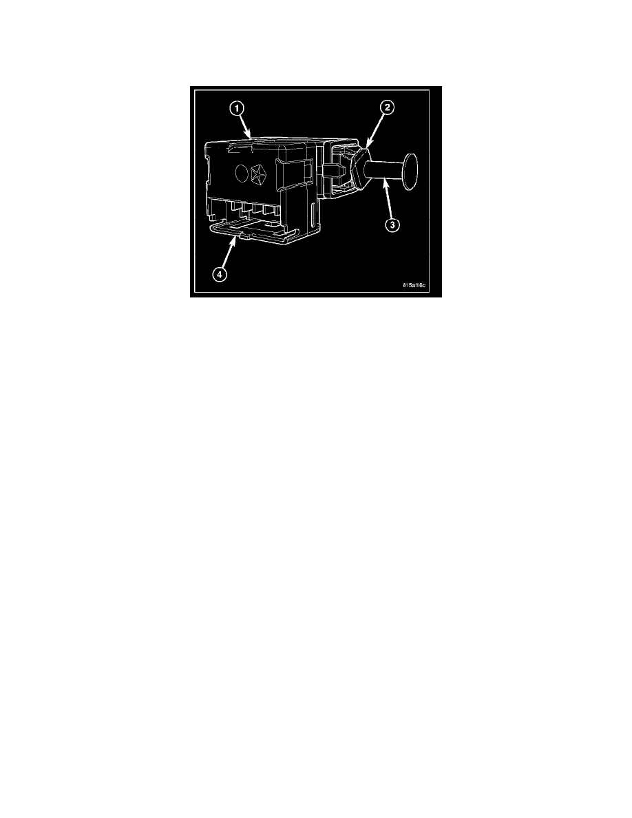
The brake lamp switch (1) is a three circuit, springloaded plunger actuated switch that is secured to the brake pedal support bracket under the instrument
panel on the driver side of the vehicle. The molded plastic switch housing has an integral connector receptacle (4) containing six terminal pins. The
switch is connected to the vehicle electrical system through a dedicated take out of the headlamp and dash wire harness.
The switch plunger (3) extends through a mounting collar (2) on one end of the switch housing. The plunger has a telescoping self-adjustment feature
that is activated after the switch is installed by pulling the brake pedal upward to its normal at rest position. The telescoping plunger can be pulled
outward from the switch housing to repeat the self-adjustment procedure if necessary.
The brake lamp switch cannot be repaired. If the switch is damaged or faulty it must be replaced with a new unit.
OPERATION
The brake lamp switch controls three independent circuits. These circuits are described as follows:
-
Brake Lamp Switch Circuit - A normally open brake lamp switch circuit receives a battery voltage input, and supplies this battery voltage to the
brake lamps and the Controller Antilock Brake (CAB) on a brake lamp switch output circuit only when the brake pedal is depressed (brake lamp
switch plunger released).
-
Brake Lamp Switch Signal Circuit - A normally closed brake lamp switch signal circuit receives a direct path to ground, and supplies this
ground input to the Powertrain Control Module (PCM) on a brake lamp switch sense circuit only when the brake pedal is released (brake lamp
switch plunger is depressed).
-
Speed Control Circuit - A normally closed speed control circuit receives a battery voltage input from the Powertrain Control Module on a speed
control supply circuit, and supplies this battery voltage to the speed control servo solenoids (dump, vacuum, and vent) on a speed control brake
switch output circuit only when the speed control system is turned On and the brake pedal is released (brake lamp switch plunger is depressed).
The brake lamp switch is diagnosed using conventional diagnostic tools and methods.