
Liberty 2WD L4-2.4L VIN 1 (2005)
Hose/Line HVAC: Testing and Inspection
Refrigerant System Charge Level
WARNING: REFER TO THE APPLICABLE WARNINGS AND CAUTIONS FOR THIS SYSTEM BEFORE PERFORMING THE
FOLLOWING OPERATION. FAILURE TO FOLLOW THE WARNINGS AND CAUTIONS COULD RESULT IN POSSIBLE PERSONAL
INJURY OR DEATH.
NOTE: Always refer to the A/C Underhood Specification Label for the refrigerant fill capacity of the vehicle being serviced.
The following procedure should be used to determine whether the A/C refrigerant system contains the proper refrigerant charge. Symptoms of an
improper refrigerant charge (low) include: poor A/C performance, fog emitted from the air outlets, a hissing sound from the A/C orifice tube/liquid line
area. There are two different methods with which the refrigerant charge level may be tested:
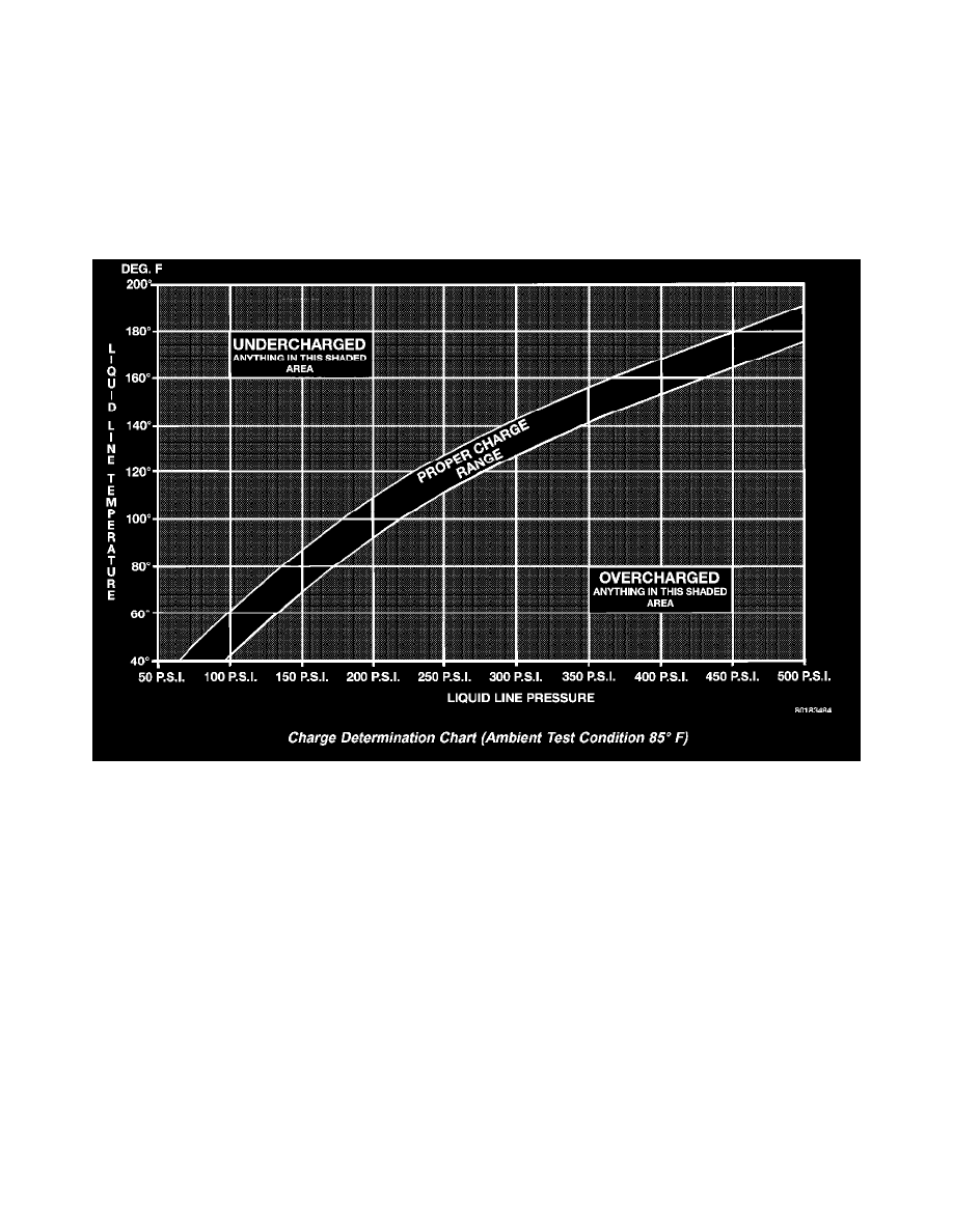
Chart Determination Chart (Ambient Test Condition 85 Degree F)
1. Using a scan tool, a thermocouple and the Charge Determination Chart.
2. Using a manifold gauge set, a thermocouple and the Charge Determination Chart.
A temperature probe is required to measure liquid line temperature. The clamp-on, Type K thermocouple temperature probe used in this procedure is
available through the DaimlerChrysler Professional Service Equipment (PSE) program. This probe (PSE #66-324-0014 or #80PK-1A) is compatible
with temperature-measuring instruments that accept Type K thermocouples, and have a miniature connector input. Other temperature probes are
available through aftermarket sources; however, all references in this procedure will reflect the use of the probe made available through the PSE
program.
In order to use the temperature probe, a digital thermometer will also be required. If a digital thermometer is not available, an adapter is available
through the PSE program that will convert any standard digital multimeter into a digital thermometer. This adapter is designed to accept any standard
Type K thermocouple. If a digital multimeter is not available, this tool is also available through the PSE program.
NOTE: When connecting the service equipment couplings to the refrigerant system service ports, be certain that the valve of each coupling is fully
closed. This will reduce the amount of effort required to make the connection.
1. Remove the caps from the refrigerant system service ports and attach a manifold gauge set or a R-134a refrigerant recovery/recycling /charging
station that meets SAE Standard J2210 to the refrigerant system.
2. Attach a clamp-on thermocouple to the A/C liquid line. The thermocouple must be placed as close as possible to the inlet end of the A/C orifice
tube to accurately observe liquid line temperature.
3. Bring the refrigerant system up to operating temperature and pressure. This is done by allowing the engine to run at idle under the following