
Liberty 4WD L4-2.4L DOHC VIN 1 (2005)
Relay Box: Description and Operation
Junction Block
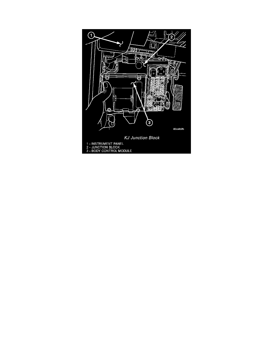
KJ Junction Block
An electrical Junction Block (JB) is concealed behind the left outboard end of the instrument panel on left hand drive vehicles. On right hand drive
vehicles the Junction Block is concealed behind the right outboard end of the instrument panel. The junction block simplifies and centralizes numerous
electrical components and distributes electrical current to many of the accessory systems throughout the vehicle. It also eliminates the need for numerous
splice connections and serves in place of a bulkhead connector between many of the engine compartment, instrument panel, and body wire harnesses.
The junction block houses up to thirty-nine mini blade-type fuses, up to three blade-type automatic resetting circuit breakers, up to three International
Standards Organization (ISO) relays and up to eleven International Standards Organization (ISO) micro-relays.
The junction block also provides the mounting location for the Body Control Module (BCM) and Remote Keyless Entry (RKE) Module. Refer to the
Electronic Control Modules section for more information on these two modules. The body control module is secured to the junction block assembly with
four screws and multiple electrical coelectrical The remote keyless entry module is mounted on the body control module via a single built-in electrical
connector. With the junction block in its normal mounting location the body control module and remote keyless entry module are not accessible.
The molded plastic junction block housing has two integral mounting bosses that are secured with two screws to the left instrument panel end bracket on
left hand drive. Additionally, upper and lower mounting brackets are attached to the junction block. These brackets are also secured to the instrument
panel with two screws. On right hand drive vehicles, the junction block is secured to the right instrument panel end bracket on right hand drive. The left
or right instrument panel end caps have snap-fit fuse access panels that can be removed for service of the junction block mounted fuses, daytime running
lamp or high beam headlamp relays. A fuse puller and spare fuse holders are located on the back of the fuse access cover, as well as an adhesive-backed
fuse layout map to ensure proper fuse identification. Refer to the owners manual or Wiring section of this manual for detailed component location and/or
identification.
The junction block unit cannot be repaired and is only serviced as an assembly. If any internal circuit or the junction block housing is faulty or damaged,
the entire junction block unit must be replaced.
All of the circuits entering and exiting the junction block do so through wire harness connectors or the body control module which is mounted directly to
the junction block underneath the instrument panel. These components are connected to the junction block through integral connector receptacles molded
into the junction block housing. Internal connection of all of the junction block circuits is accomplished by an intricate combination of hard wiring and
bus bars. Refer to Wiring Diagrams for the location of complete junction block circuit diagrams.