
Liberty 4WD L4-2.8L DSL Turbo VIN 5 (2006)
Power Seat Control Module: Testing and Inspection
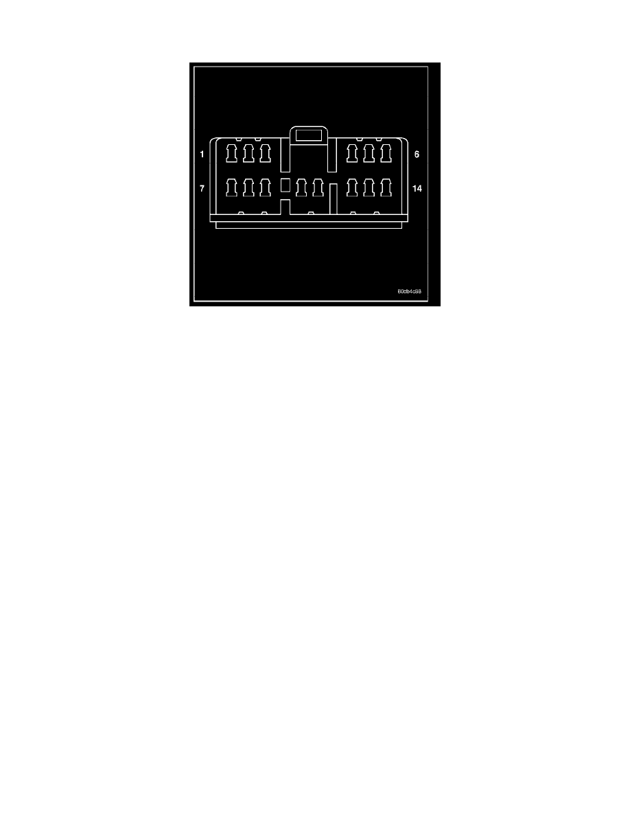
HEATED SEAT MODULE
If a heated seat fails to heat and one or both of the indicator lamps on a heated seat switch flash, refer Heated Seat System Diagnosis and Testing Heated
Systems for flashing LED failure identification. Refer to Wiring Diagrams in for complete heated seat system wiring diagrams.
1. Remove the heated seat module from its mounting location.
NOTE: Any resistance values (ohms V) given in the following text are supplied using the automatic range generated by a fluke automotive meter. If
another type of measuring device is used the values generated may not be the same as the results shown here, or may have to be converted to the range
used here.
RIGHT SEAT HEATER INOPERATIVE
1. If a heated seat heats but one or both indicator lamps (LED's) on the heated seat switch fail to illuminate, check the driver circuit with the
inoperative LED for a short to ground. If OK, replace the heated seat switch. If NOT OK repair the short to ground as required and than replace
the heated seat switch.
NOTE: If the right seat cushion is already warm the following step will not prove conclusive.
2. Back-probe the heated seat module wire harness connector, do not disconnect. Check cavity #3 for battery voltage when the right heated seat
switch is turned "ON", voltage should be present, If OK go to Step 3 If NOT OK, test the right heated seat switch. If the switch tests OK, check for
continuity between the switch and control module on the MUX circuit, If OK replace the heated seat control module. If NOT OK, repair the open
or shorted MUX circuit as required.
NOTE: Be certain the battery is fully charged before testing. Failure to do so can result in incorrect readings.
3. Back-probe the heated seat module wire harness connector, do not disconnect. Check cavity #10 for battery voltage, while observing the voltmeter
depress the right heated seat switch low setting twice, voltage should toggle between approx.12v and 8v, If OK go to Step 4. If NOT OK check for
continuity between the switch and control module on the low heat driver circuit, If OK replace the heated seat control module.
4. Back-probe the heated seat module wire harness connector, do not disconnect. Check cavity #11 for battery voltage, while observing the voltmeter
depress the right heated seat switch high setting twice, voltage should toggle between approx.12v and 8v, If OK go to Step 5. If NOT OK check
for continuity between the switch and control module on the high heat driver circuit, If OK replace the heated seat control module.
5. Back-probe the heated seat module wire harness connector, do not disconnect. Check cavity #2 for approx. 5v, voltage should be present, If OK go
to Step 6. If NOT OK replace the heated seat control module.
6. Back-probe the heated seat module wire harness connector, do not disconnect. Check cavity #7 for a range in voltage from 1.72v (warm seat) -
3.0v (cold seat). It should be within this range, If OK replace the heated seat module. If NOT OK test the Heated Seat Sensor. If NOT OK, replace
the right heated seat element and sensor assembly. If the heated seat sensor tests OK, check for continuity between the right heated seat cushion
connector and control module connector on the 5v supply circuit, If NOT OK, repair the open or shorted 5v supply circuit as required. If OK
check for continuity between the right heated seat cushion connector and control module connector on the temperature sensor input circuit. If NOT
OK, repair the open or shorted temperature sensor input circuit as required. If OK replace the heated seat control module.
LEFT SEAT HEATER INOPERATIVE
1. If a heated seat heats but one or both indicator lamps (LED's) on the heated seat switch fail to illuminate, check the driver circuit with the