
Liberty Sport 2WD L4-2.4L VIN 1 (2002)
Audible Warning Device: Description and Operation
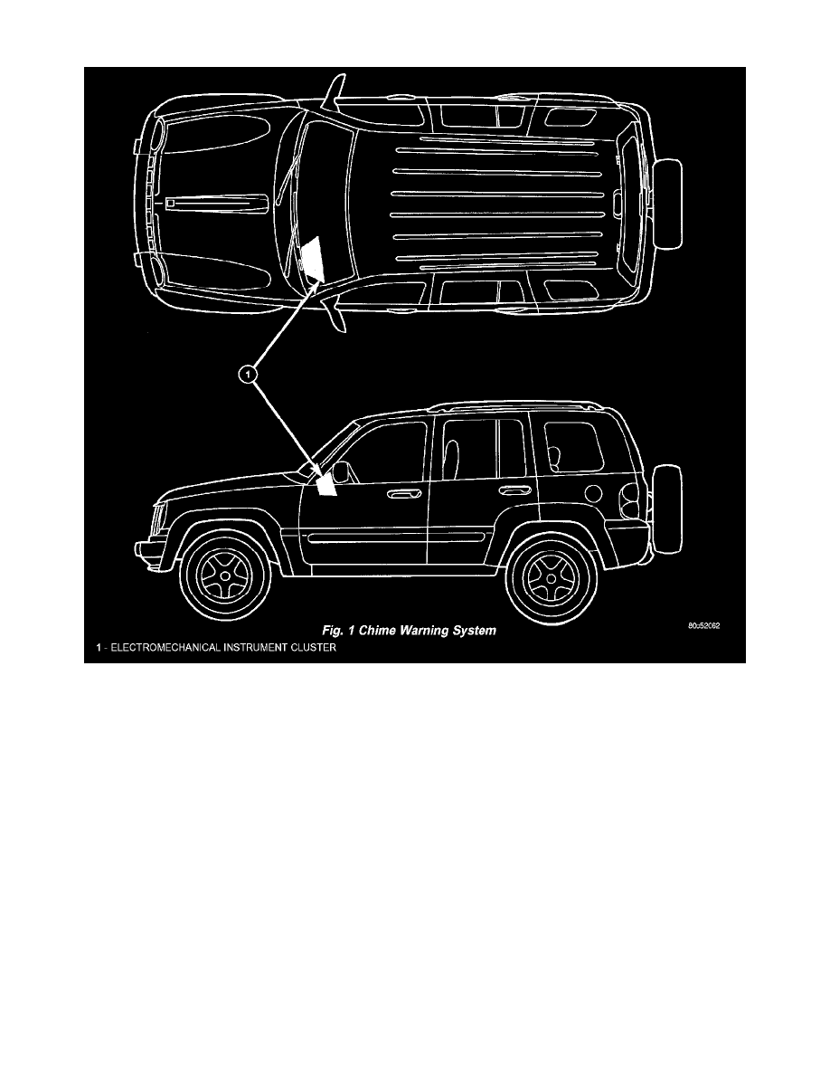
Fig.1 Chime Wiring System
CHIME/BUZZER
Chime Warning System
A chime warning system is standard factory-installed equipment on this model. The chime warning system uses a single chime tone generator that
is soldered onto the electronic circuit board that is integral to the ElectroMechanical Instrument Cluster (EMIC) to provide an audible indication
of various vehicle conditions that may require the attention of the vehicle operator or occupants (Fig. 1). The microprocessor-based EMIC utilizes
electronic chime request messages received from other electronic modules in the vehicle over the Programmable Communications Interface (PCI)
data bus network along with hard wired inputs to the cluster microprocessor to monitor many sensors and switches throughout the vehicle. In
response to those inputs, the integrated circuitry and internal programming of the EMIC allow it to control audible outputs that are produced
through its on-board chime tone generator.
The EMIC circuitry and its chime tone generator are capable of producing each of the four following audible outputs:
-
Fixed Duration Beep - A short, sharp, single tactile "beep-like" tone that is about 150 milliseconds in duration.
-
Single Chime Tone - A single "bong-like" chime tone.
-
Slow Rate Repetitive Chime - Repeated chime tones that are issued at a slow rate of about 50 "bong-like" tones per minute.
-
Fast Rate Repetitive Chime - Repeated chime tones that are issued at a fast rate of about 180 "bong-like" tones per minute.
Hard wired circuitry connects the EMIC and the various chime warning system switch and sensor inputs to their electronic modules and to each
other through the electrical system of the vehicle. These hard wired circuits are integral to numerous wire harnesses, which are routed throughout
the vehicle and retained by many different methods. These circuits may be connected to each other, to the vehicle electrical system and to the
chime warning system through the use of a combination of soldered splices, splice block connectors, and many different types of wire harness
terminal connectors and insulators. Refer to the appropriate wiring information. The wiring information includes wiring diagrams, proper wire and