
Liberty Sport 4WD L4-2.4L VIN 1 (2002)
Micro ISO Relay: Testing and Inspection
MICRO-RELAY TEST
1. Remove the relay from its mounting location.
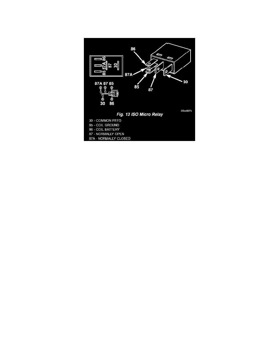
Fig.13 ISO Micro Relay
2. A relay in the de-energized position should have continuity between terminals 87A and 30, and no continuity between terminals 87 and 30. If OK,
go to Step 3. If not OK, replace the faulty relay
3. Resistance between terminals 85 and 86 (electromagnet) should be 67.5 - 82.5 ohms. If OK, go to Step 4. If not OK, replace the faulty relay
4. Connect a battery to terminals 85 and 86.There should now be continuity between terminals 30 and 87, and no continuity between terminals 87A
and 30. If OK, reinstall the relay and use a DRBIII scan tool to perform further testing. Refer to the appropriate diagnostic information.
Refer to the appropriate wiring information. The wiring information includes wiring diagrams, proper wire and connector repair procedures, details of
wire harness routing and retention, connector pin-out information and location views for the various wire harness connectors, splices and grounds.