
Wagoneer L6-258 4.2L VIN C 2-bbl (1982)
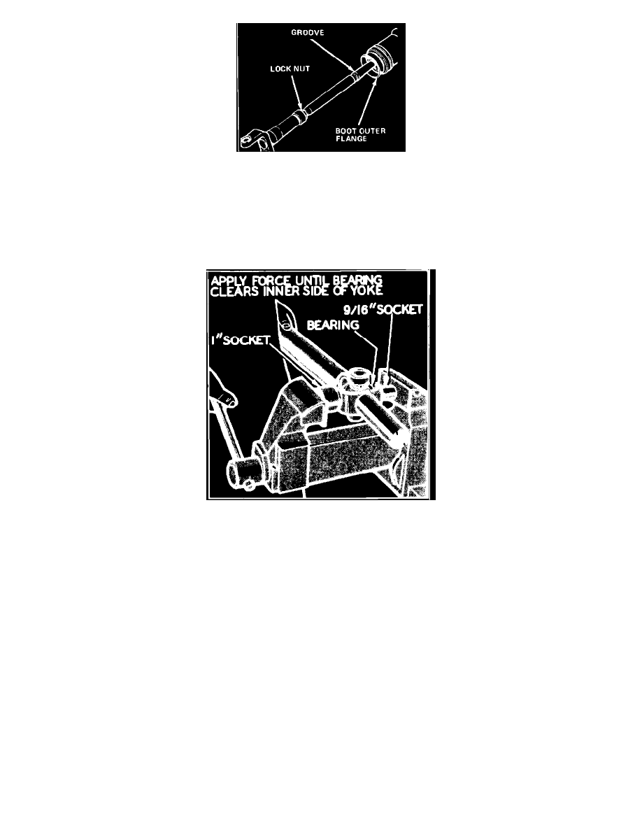
Fig. 4 Adjusting front propeller shaft length
Top image shows a typical example of universal joints of this type. They all operate on the same principle and similar service and replacement
procedures may be applied to all.
On some models, whenever the front propeller shaft has been removed, the shaft length should be checked and adjusted as necessary. To check
adjustment, support vehicle so that axles are supporting vehicle weight, then measure from rear edge of groove on shaft to outer flange of rubber boot,.
Measurement should be 1.5-1.75 inch. If dimension is not as specified, loosen slip yoke locknut, slide shaft in or out as required, then torque locknut
to 55 ft. lbs.
Fig. 5 Removing bearings from yoke using a small socket as a driver & large socket as a receiver
Disassembly
1. Remove snap rings (or retainer plates) that retain bearings in yoke and drive shaft.
2. Place U-joint in a vise.
3. Select a wrench socket with an outside diameter slightly smaller than the U-joint bearings. Select another wrench socket with an inside diameter
slightly larger than the U-joint bearings.
4. Place the sockets at opposite bearings in the yoke so that the smaller socket becomes a bearing pusher and the larger socket becomes a bearing
receiver when the vise jaws come together. Close vise jaws until both bearings are free of yoke and remove bearings from the cross or spider.
5. If bearings will not come all the way out, close vise until bearing in receiver socket protrudes from yoke as much as possible without using
excessive force. Then remove from vise and place that portion of bearing which protrudes from yoke between vise jaws. Tighten vise to hold
bearing and drive yoke off with a soft hammer.
6. To remove opposite bearing from yoke, replace in vise with pusher socket on exposed cross journal with receiver socket over bearing cup. Then
tighten vise jaws to press bearing back through yoke into receiving socket.
7. Remove yoke from drive shaft and again place protruding portion of bearing between vise jaws. Then tighten vise to hold bearing while driving
yoke off bearing with soft hammer.
8. Turn spider or cross 1/4 turn and use the same procedure to press bearings out of drive shaft.