
Wrangler 2WD V6-3.8L (2008)
Keyless Entry Module: Service and Repair
Installation
INSTALLATION
WARNING: To avoid serious or fatal injury on vehicles equipped with airbags, disable the Supplemental Restraint System (SRS) before
attempting any steering wheel, steering column, airbag, seat belt tensioner, impact sensor, or instrument panel component diagnosis or service.
Disconnect and isolate the battery negative (ground) cable, then wait two minutes for the system capacitor to discharge before performing
further diagnosis or service. This is the only sure way to disable the SRS. Failure to take the proper precautions could result in accidental
airbag deployment.
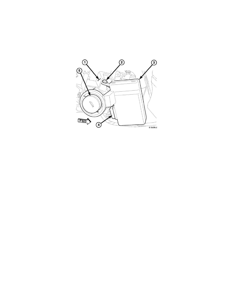
1. Position the Sentry Key REmote Entry Module (SKREEM) (3) onto the steering column ignition lock housing with the antenna ring oriented
around the lock cylinder (5).
2. Install and tighten the screw (2) that secures the SKREEM mounting bracket to the boss on the top of the ignition lock housing. Tighten the screw
to 2 Nm (20 in. lbs.).
3. Reconnect the instrument panel wire harness connector (4) to the SKREEM connector receptacle.
4. Reinstall the right multi-function switch onto the integral mounting bracket (1) on the right side of the clockspring. See: Sensors and
Switches/Sensors and Switches - Wiper and Washer Systems/Wiper Switch/Service and Repair/Installation.
5. Reconnect the battery negative cable.
NOTE: On vehicles equipped with the Sentry Key Immobilizer System (SKIS), when the SKREEM is replaced with a new unit, a
diagnostic scan tool MUST be used to initialize the new SKREEM and to program at least two Sentry Key transponders before the
vehicle can be operated. See: Accessories and Optional Equipment/Antitheft and Alarm Systems/Testing and Inspection/Programming
and Relearning.
NOTE: On vehicles equipped with a Tire Pressure Monitoring (TPM) system and a full-sized matching spare tire and wheel assembly, when the
SKREEM or the spare tire pressure sensor is replaced with a new unit, a diagnostic scan tool MUST be used to run a routine that allows the
SKREEM to be programmed with the ID number and location of the spare tire pressure sensor mounted in the wheel of the spare tire. This
may be done using a TPM-RKE Analyzer special tool by following the programming steps outlined in the diagnostic scan tool for Program Tire
Sensor ID w/TPM Tool under Miscellaneous Functions for the WCM/Wireless Control Module menu item. If a TPM-RKE Analyzer special
tool is not available, the spare tire must be dismounted from its wheel to access and note the ID number on the spare tire pressure sensor so that
the ID code for that sensor can be programmed into the new SKREEM. Follow the programming steps outlined in the diagnostic scan tool for
Learn Spare Tire Sensor ID also found under Miscellaneous Functions for the WCM/Wireless Control Module menu item. See: Instrument
Panel, Gauges and Warning Indicators/Tire Monitoring System/Tire Pressure Sensor/Service and Repair/Installation.