
Wrangler 4WD L4-150 2.5L VIN P MFI (1998)
NOTE: When replacing inserts, the odd size inserts must be either all on the top (in cylinder block) or all on the bottom (in main bearing cap).
Once the bearings have been properly fitted, proceed to Crankshaft Main Bearing-Installation.
BEARING-TO-JOURNAL CLEARANCE (CRANKSHAFT INSTALLED)
When using Plastigage, check only one bearing clearance at a time.
Install the grooved main bearings into the cylinder block and the non-grooved bearings into the bearing caps.
Install the crankshaft into the upper bearings dry.
Place a strip of Plastigage across full width of the crankshaft journal to be checked.
Install the bearing cap and tighten the bolts to 108 Nm (80 ft. lbs.) torque.
NOTE: DO NOT rotate the crankshaft. This will cause the Plastigage to shift, resulting in an inaccurate reading. Plastigage must not be permitted to
crumble. If brittle, obtain fresh stock.
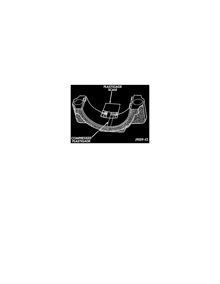
Remove the bearing cap. Determine the amount of clearance by measuring the width of the compressed Plastigage with the scale on the Plastigage
envelope. (Refer to Specifications for the proper clearance.
Plastigage should indicate the same clearance across the entire width of the insert. If clearance varies, it may indicate a tapered journal or foreign
material trapped behind the insert.
If the specified clearance is indicated and there are no abnormal wear patterns, replacement of the bearing inserts is not necessary. Remove the
Plastigage from the crankshaft journal and bearing insert. Proceed to Crankshaft Main Bearing-Installation.
If the clearance exceeds specification, install a pair of 0.025 mm (0.001 in.) undersize bearing inserts and measure the clearance as described in the
previous steps.
The clearance indicated with the 0.025 mm (0.001 in.) undersize insert pair installed will determine if this insert size or some other combination will
provide the specified clearance. FOR EXAMPLE: If the clearance was 0.0762 mm (0.003 in.) originally, a pair of 0.0254 mm (0.001 in.) undersize
inserts would reduce the clearance by 0.0254 mm (0.001 in.). The clearance would then be 0.0508 mm (0.002 in.) and within the specification. A
0.051 mm (0.002 in.) undersize bearing insert and a 0.0254 mm (0.001 in.) undersize insert would reduce the original clearance an additional 0.0127
mm (0.0005 in.). The clearance would then be 0.0381 mm (0.0015 in.).
CAUTION: Never use a pair of inserts that differ more than one bearing size as a pair.
FOR EXAMPLE: DO NOT use a standard size upper insert and a 0.051 mm (0.002 in.) undersize lower insert.
If the clearance exceeds specification using a pair of 0.051 mm (0.002 in.) undersize bearing inserts, measure crankshaft journal diameter with a
micrometer. If the journal diameter is correct, the crankshaft bore in the cylinder block may be misaligned, which requires cylinder block replacement
or machining to true bore.
If journals 1 through 5 diameters are less than 63.4517 mm (2.4981 in.), replace crankshaft or grind crankshaft down to accept the appropriate
undersize bearing inserts.
Once the proper clearances have been obtained, proceed to Crankshaft Main Bearing-Installation.