
Under bonnet - harness routing
- Make
- Land Rover
- Model
- Defender Technical Bulletins
- Section
- Under bonnet - harness routing › Under bonnet - harness routing
UNDER BONNET - HARNESS ROUTING
- Model
- Defender
- Reference
- Service action 234
Bulletin text
SERVICE ACTION BULLETIN
Circulation: X Indicates to whom this information should be circulated SERVICE MANAGER SERVICE RECEPTION PARTS MANAGER WARRANTY MANAGER
Defender Tdi Diesel - Ministry of Defence ‘WOLF/PULSE’ derivatives
Build date
PROBLEM:
UNDER BONNET - HARNESS ROUTING
CAUSE:
It has been identified that during vehicle manufacture inconsistant underbonnet harness routing may cause harnesses to run close to hot engine components.
ACTION:
At the first available opportunity, inspect vehicles within the above VIN range and re-route harnesses as necessary.
CONTACT - Those markets who have a pre-arranged working relationship with local Defence bases or Govermental Departments, are advised to contact them to arrange a re-work programme.
PROCEDURE
Procedure - Harness re-routing
General guidelines for 1 st alternator power harness rework: • All work to be conducted with the vehicle battery negative terminal disconnected. • Position all ‘screwed’ harness connectors in the 12 o’clock position and retighten. • Ensure there is no contact between the alternator harness and any potentially hot surfaces. • Ensure there is no contact between the alternator harness and any under bonnet feature that would cause ‘chafing’ of the harness. Insulate any area with tape that has appeared to have chafed. • If connector position and harness routing are correct after inspection, check all connections for security in all cases (vehicles fitted with field radios have two alternators). • Ensure terminal covers or insulator ‘boots’ are positioned correctly and not straining or damaged. Adjust as necessary.
SERVICE ACTION BULLETIN No:A/D234
EN Bull. N o : A/D234 1 14/02/01 Page: 1 of 4
AFFECTED RANGE:
TA991819 to TA999991 VA100128 to XA163119
May 1996 to October 1998
Land Rover 2001
• Check alternator harness routing for satisfactory clipping where provided, also ensure that the harness is not tightly routed or pulling around any componentry, sharp edges or corners.
General guidelines for 2 nd (radio) alternator power harness rework: • All work to be conducted with the vehicle battery negative terminal disconnected. • Check all connections for security and tighten as necessary. • Ensure there is no contact between the alternator harness and any under bonnet feature that would cause ‘chafing’ of the harness. Insulate any area with tape that has appeared to have chafed. • Ensure terminal covers or insulator ‘boots’ are positioned correctly and not straining or damaged. Adjust as necessary. • Check alternator harness routing for satisfactory clipping where provided, also ensure that the harness is not tightly routed or pulling around any componentry, sharp edges or corners.
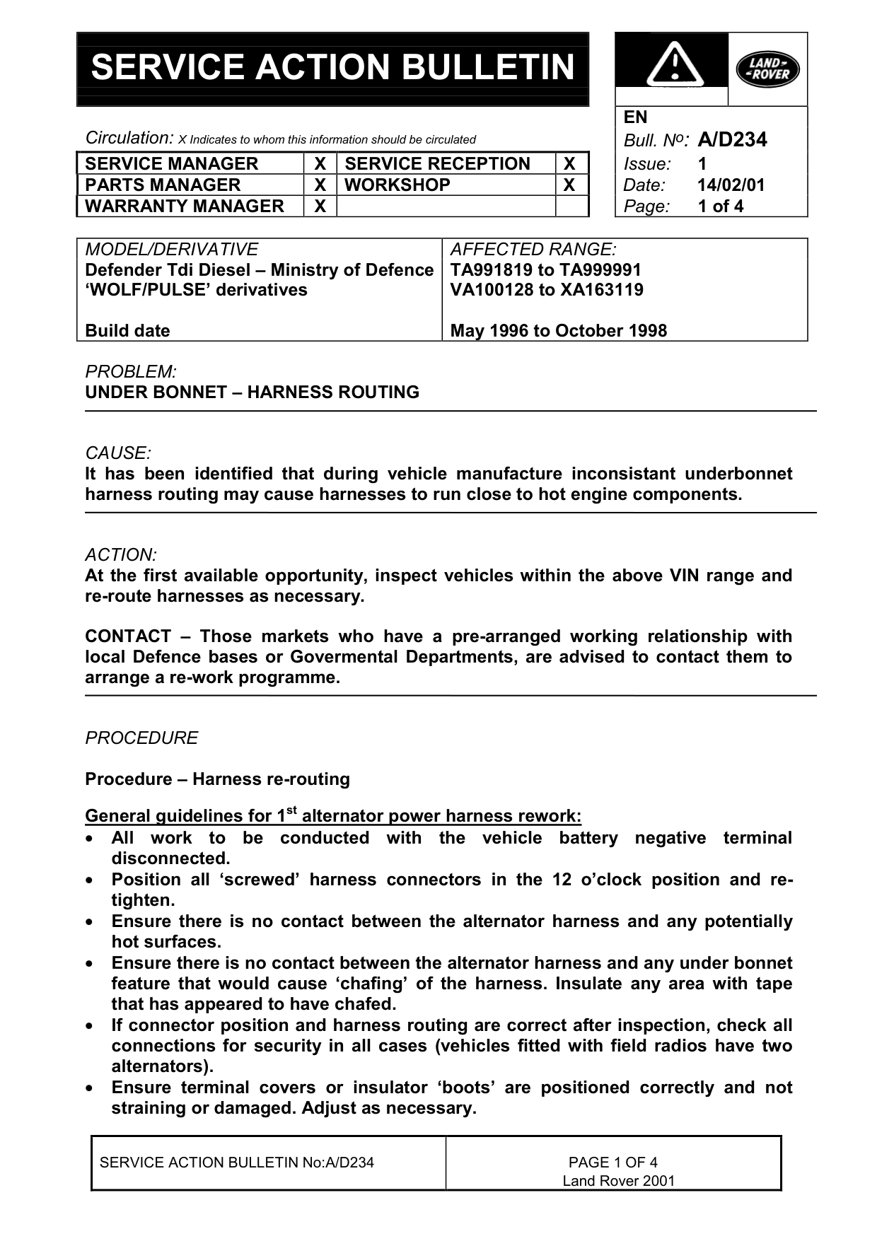
Non EGR Tdi engine derivatives: 1. Viewing the rear of the alternator fig 1, if the power unit harness connections are at the 2 or 3 o’clock or in any other position other than the 12 o’clock position they must be slackened off and re-tightened to the 12 o’clock position as shown in fig 2. This will allow the harness to be routed correctly around the alternator.
2. Check all other harness routing to ensure no foul or chafe conditions exist.
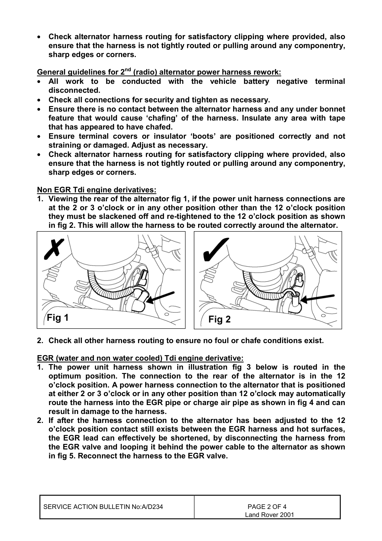
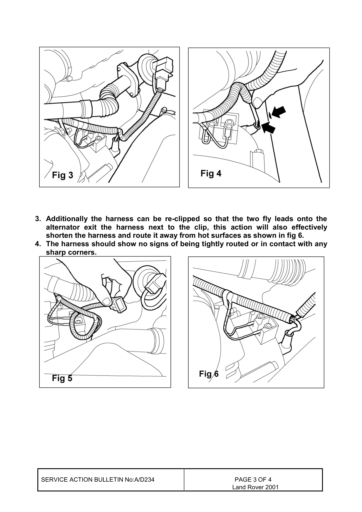
EGR (water and non water cooled) Tdi engine derivative: 1. The power unit harness shown in illustration fig 3 below is routed in the optimum position. The connection to the rear of the alternator is in the 12 o’clock position. A power harness connection to the alternator that is positioned at either 2 or 3 o’clock or in any other position than 12 o’clock may automatically route the harness into the EGR pipe or charge air pipe as shown in fig 4 and can result in damage to the harness. 2. If after the harness connection to the alternator has been adjusted to the 12 o’clock position contact still exists between the EGR harness and hot surfaces, the EGR lead can effectively be shortened, by disconnecting the harness from the EGR valve and looping it behind the power cable to the alternator as shown in fig 5. Reconnect the harness to the EGR valve.
SERVICE ACTION BULLETIN No:A/D234 Land Rover 2001
3. Additionally the harness can be re-clipped so that the two fly leads onto the alternator exit the harness next to the clip, this action will also effectively shorten the harness and route it away from hot surfaces as shown in fig 6. 4. The harness should show no signs of being tightly routed or in contact with any sharp corners.
SERVICE ACTION BULLETIN No:A/D234 Land Rover 2001
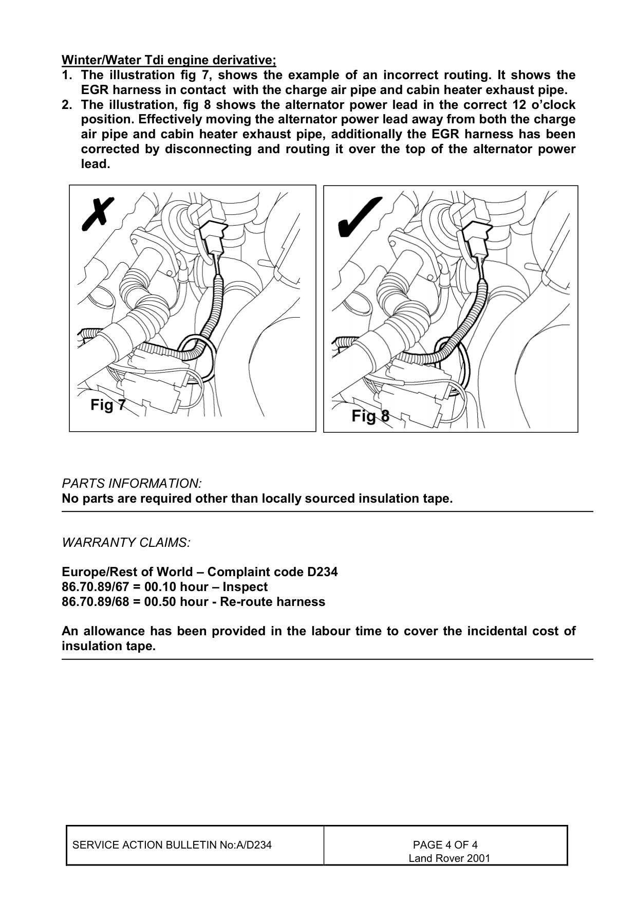
Winter/Water Tdi engine derivative; 1. The illustration fig 7, shows the example of an incorrect routing. It shows the EGR harness in contact with the charge air pipe and cabin heater exhaust pipe. 2. The illustration, fig 8 shows the alternator power lead in the correct 12 o’clock position. Effectively moving the alternator power lead away from both the charge air pipe and cabin heater exhaust pipe, additionally the EGR harness has been corrected by disconnecting and routing it over the top of the alternator power lead.
PARTS INFORMATION:
No parts are required other than locally sourced insulation tape.
WARRANTY CLAIMS:
Europe/Rest of World - Complaint code D234 86.70.89/67 = 00.10 hour - Inspect 86.70.89/68 = 00.50 hour - Re-route harness
An allowance has been provided in the labour time to cover the incidental cost of insulation tape.
SERVICE ACTION BULLETIN No:A/D234 Land Rover 2001
Parts & tools for this job For Land Rover Defender
- TOOLDigital multimeterSearch: automotive digital multimeter
- PARTAssorted fuse kitSearch: car fuse assortment kit
- TOOLWire crimper and connector kitSearch: wire crimper connector kit
Links open Amazon search results in a new tab. As an Amazon Associate I earn from qualifying purchases.