
TESTING IN POSITION
- Make
- Land Rover
- Model
- Defender 300Tdi Defender
- Section
- TESTING IN POSITION
ELECTRICAL
1
FAULT DIAGNOSIS
GENERAL INFORMATION
Detailed information of electrical systems, component
locations and circuit diagrams are covered in the
Defender Electrical Troubleshooting Manual.
This section covers checks of the charging system.
GENERATOR TESTING
Service repair no - 86.10.01
Charging system check
1. Check battery is in good condition, with an open
circuit voltage of at least 12.6 V. Recharge or
substitute battery to carry out test.
2. Check drive belt condition
See SECTION 10,
Maintenance, Under bonnet maintenance.
3. Check battery connections are clean and tight.
4. Check generator connections are clean and
tight.
5. Ensure there is no drain on battery from, for
example, interior or exteriorlamps.
Generator test
Following instructions refer to use of suitable test
equipment using a carbon pile rheostat.
6. Connect test equipment referring to
manufacturer’s instructions.
7. Start engine and run at 3000 rev/min without
accessory load.
8. Rotate carbon pile load control to achieve
greatest output (amps) without allowing voltage
to fall below 12.0 V. A reading in amps, of
generator output should be obtained.
9. Run engine at 3000 rev/min, switch selector to
regulator test, read voltmeter. A reading of 13.6
to 14.4 V should be obtained.
10. Switch selector to diode/stator test, switch on
headlamps to load generator. Raise engine
speed to 3000 rev/min, read voltmeter, needle
must be within ’OK’ range.
TESTING IN POSITION
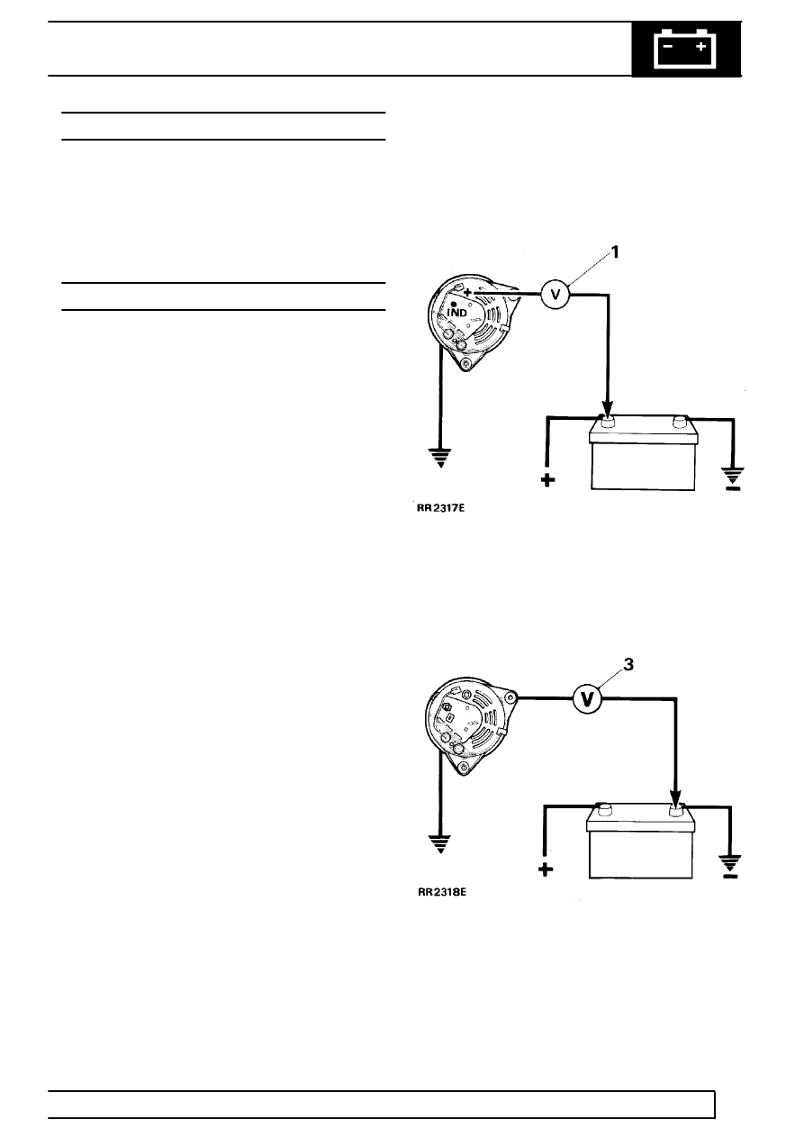
Charging circuit resistance test.
1. Connect a low range voltmeter between
generator terminal marked B+ and positive
terminal of battery.
2. Switch on headlamps, start engine. Run engine
at approximately 3000 rev/min. Note voltmeter
reading.
3. Transfer voltmeter connections to frame of
generator and negative terminal of battery, and
again note voltmeter reading.
4. If reading exceeds 0.5 volt on positive side or
0.25 volt on negative side, there is a high
resistance in charging circuit which must be
traced and remedied.
Parts & tools for this job For Land Rover Defender
- TOOLDigital multimeterSearch: automotive digital multimeter
- PARTAssorted fuse kitSearch: car fuse assortment kit
- TOOLWire crimper and connector kitSearch: wire crimper connector kit
Links open Amazon search results in a new tab. As an Amazon Associate I earn from qualifying purchases.